
Controlled nucleation during freezing step of freeze drying cycle using pressure differential ice crystals distribution from condensed frost

a technology of condensed frost and controlled nucleation, which is applied in the direction of drying, drying solid materials without heat, lighting and heating apparatus, etc., can solve the problems of increased nucleation time, increased cost and complexity, and reduced uniformity of products, so as to improve control nucleation performance and reduce the size of the condensing chamber , the effect of improving the nucleation process

Active Publication Date: 2014-11-04
MILLROCK TECH
View PDF5 Cites 14 Cited by
  • Summary
  • Abstract
  • Description
  • Claims
  • Application Information

AI Technical Summary

Benefits of technology

[0010]In the new and improved method of the present invention, an ice fog is not formed inside the product chamber by the introduction of a cold gas, e.g., liquid nitrogen chilled gas at −196° C., which utilizes the humidity inside the product chamber to produce the suspension of small ice particles in accordance with known methods in the prior art. These known methods have resulted in increased nucleation time, reduced uniformity of the product in different vials in a freeze drying apparatus, and increased expense and complexity because of the required nitrogen gas chilling apparatus.
[0012]It has now been determined that during the opening of the isolation valve the sudden change of pressure creates strong gas turbulence in the condenser chamber. This turbulence is capable of knocking off any loosely condensed frost on the condensing surface and breaks it into larger ice crystals. The larger ice crystals break away from the condensing surface and mix in the gas flow rushing into the product chamber. The larger size of the ice crystals enables them to last longer in the product chamber and to make them more effective in the nucleation process.
[0013]The larger ice crystals help to achieve consistent nucleation coverage and greatly improve controlled nucleation performance, especially when the product chamber has restriction in gas flow, such as side plates or when the vapor port is located under or above the shelf stack.
[0014]Previously the volume of suspended ice fog in gas form was limited by the condenser volume. By adding dense frost on the condensing surface, the physical volume of the condenser is no longer a limitation. The thickness of frost can easily be controlled to achieve a desired density of larger ice crystals in the product chamber during nucleation. The condensed frost method works with any condensing surface. In addition, the size of the condensing chamber may be reduced to increase the velocity of the gas in the condenser.

Problems solved by technology

These known methods have resulted in increased nucleation time, reduced uniformity of the product in different vials in a freeze drying apparatus, and increased expense and complexity because of the required nitrogen gas chilling apparatus.
It has now been determined that during the opening of the isolation valve the sudden change of pressure creates strong gas turbulence in the condenser chamber.

Method used


Image

  • Controlled nucleation during freezing step of freeze drying cycle using pressure differential ice crystals distribution from condensed frost
  • Controlled nucleation during freezing step of freeze drying cycle using pressure differential ice crystals distribution from condensed frost
  • Controlled nucleation during freezing step of freeze drying cycle using pressure differential ice crystals distribution from condensed frost

Examples


Embodiment Construction

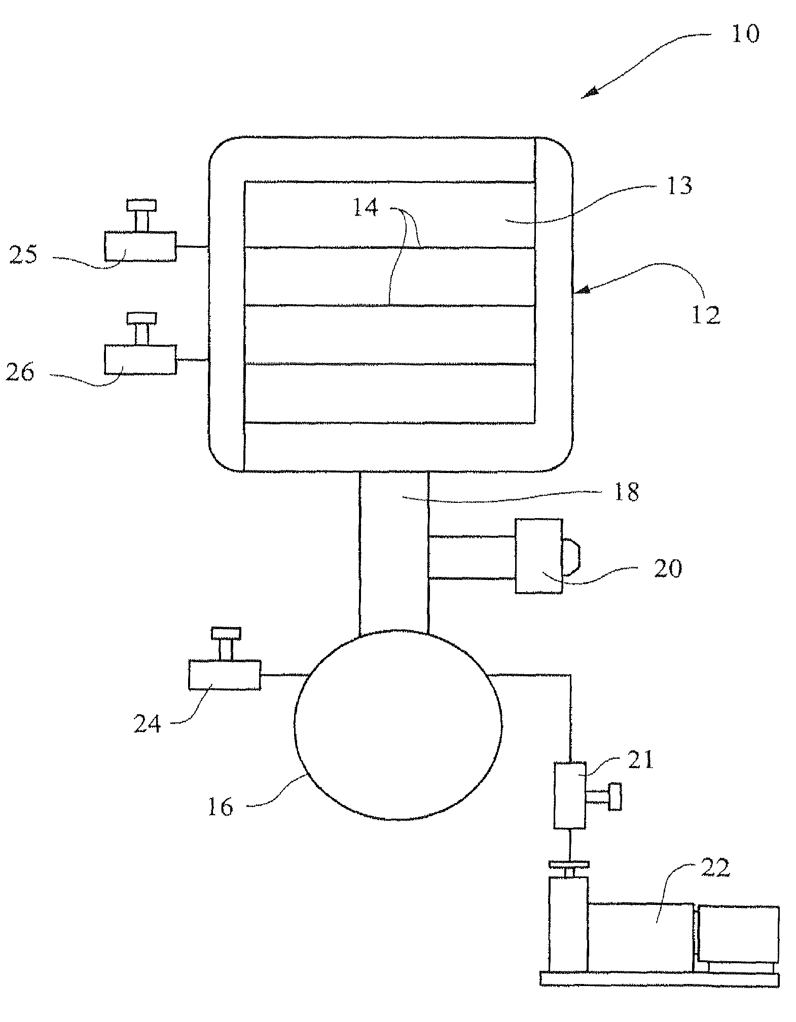
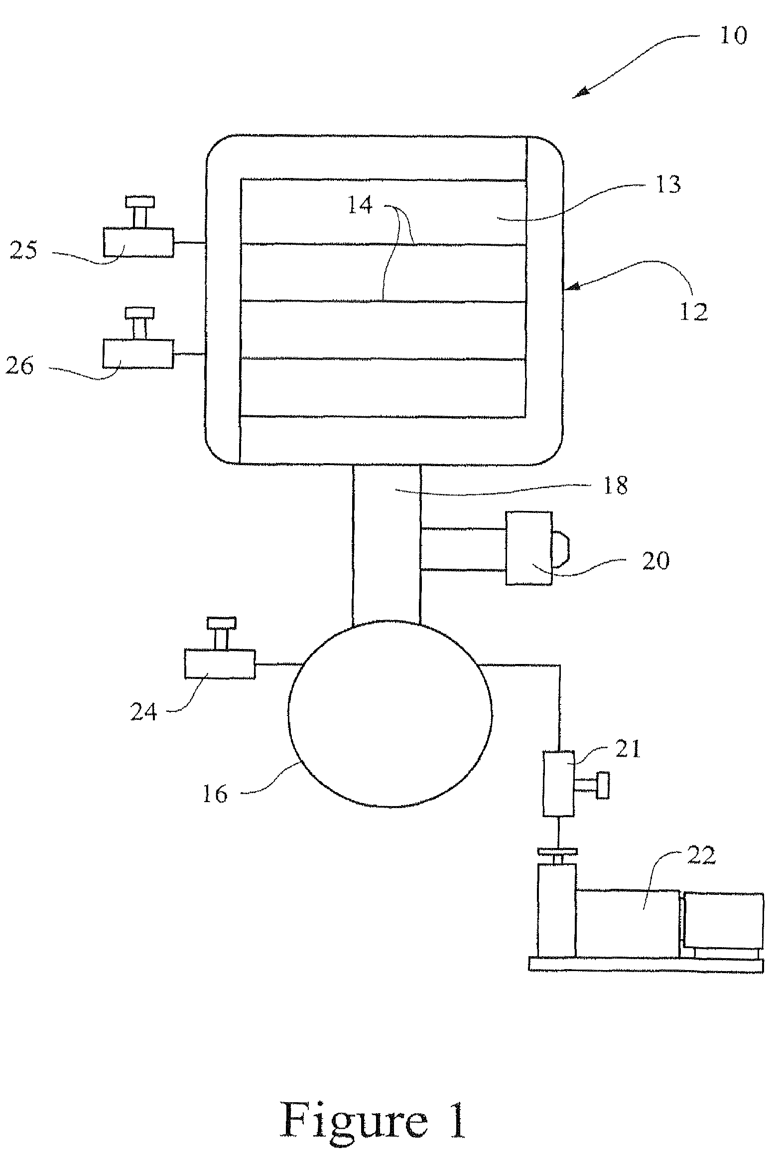
[0018]As shown in FIG. 1, an apparatus 10 for performing the method of the present invention comprises a freeze dryer 12 having one or more shelves 14 for supporting vials of product to be freeze dried. A condenser chamber 16 is connected to the freeze dryer 12 by a vapor port 18 having an isolation valve 20 of any suitable construction between the condenser chamber 16 and the freeze dryer 12. Preferably, the isolation valve 20 is constructed to seal vacuum both ways.

[0019]A vacuum pump 22 is connected to the condenser chamber 16 with a valve 21 therebetween of any suitable construction. The condenser chamber 16 has a release valve 24 of any suitable construction and the freeze dryer 12 has a control valve 25 and release valve 26 of any suitable construction. As an illustrative example, the operation of the apparatus 10 in accordance with the method of the present invention is as follows:[0020]1. Cool down the shelf or shelves 14 to a pre-selected temperature (for example −5° C.) fo...


PUM


Abstract

A method of controlling and enhancing the nucleation of product in a freeze dryer, wherein the product is maintained at a predetermined temperature and pressure in a chamber of the freeze dryer, and a predetermined volume of condensed frost is created on an inner surface of a condenser chamber separate from the product chamber and connected thereto by a vapor port. The condenser chamber has a predetermined pressure that is greater than that of the product chamber. The opening of the vapor port into the product chamber creates gas turbulence that breaks down the condensed frost into ice crystals that rapidly enter the product chamber for even distribution therein to create uniform and rapid nucleation of the product in different areas of the product chamber.

Description

BACKGROUND OF THE INVENTION[0001]1. Field of the Invention[0002]The present invention relates to a method of controlling nucleation during the freezing step of a freeze drying cycle and, more particularity, to such a method that uses a pressure differential ice fog distribution to trigger a spontaneous nucleation among all vials in a freeze drying apparatus at a predetermined nucleation temperature.[0003]2. Description of the Background Art[0004]Controlling the generally random process of nucleation in the freezing stage of a lyophilization or freeze-drying process to both decrease processing time necessary to complete freeze-drying and to increase the product uniformity from vial-to-vial in the finished product would be highly desirable in the art. In a typical pharmaceutical freeze-drying process, multiple vials containing a common aqueous solution are placed on shelves that are cooled, generally at a controlled rate, to low temperatures. The aqueous solution in each vial is coole...

Claims


Application Information

Patent Timeline
Patent Type & Authority Patents(United States)
IPC IPC(8): F26B5/06
CPCF26B5/06
Inventor LING, WEIJIA
Owner MILLROCK TECH
Learn More