

Instrument for simulating multifocal ophthalmic corrections
a technology of ophthalmology and instrument, applied in the field of instrument simulating multifocal ophthalmology, can solve the problems of inability to trial and error process, inability to tolerate well any lens design, and only viable solution for glasses, so as to reduce the actual willingness of patients, reduce the cost, and reduce the effect of image quality
- Summary
- Abstract
- Description
- Claims
- Application Information
AI Technical Summary
Benefits of technology
Problems solved by technology
Method used
Image

Examples
Embodiment Construction
General Description of the Invention
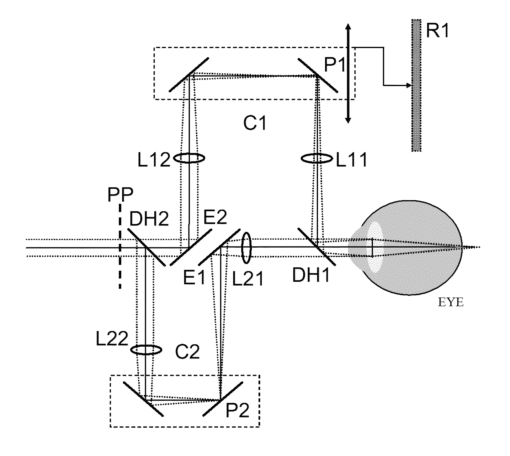
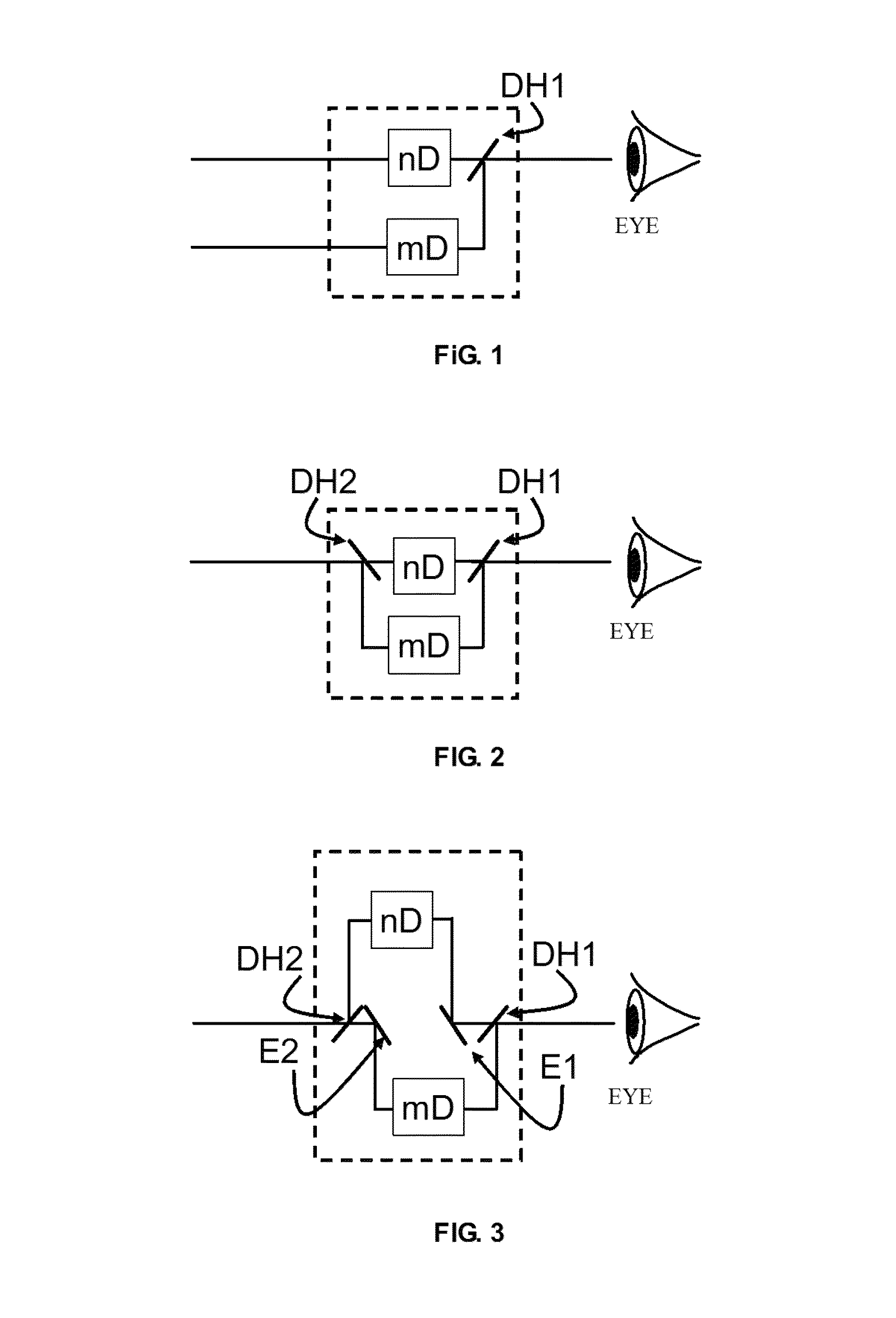
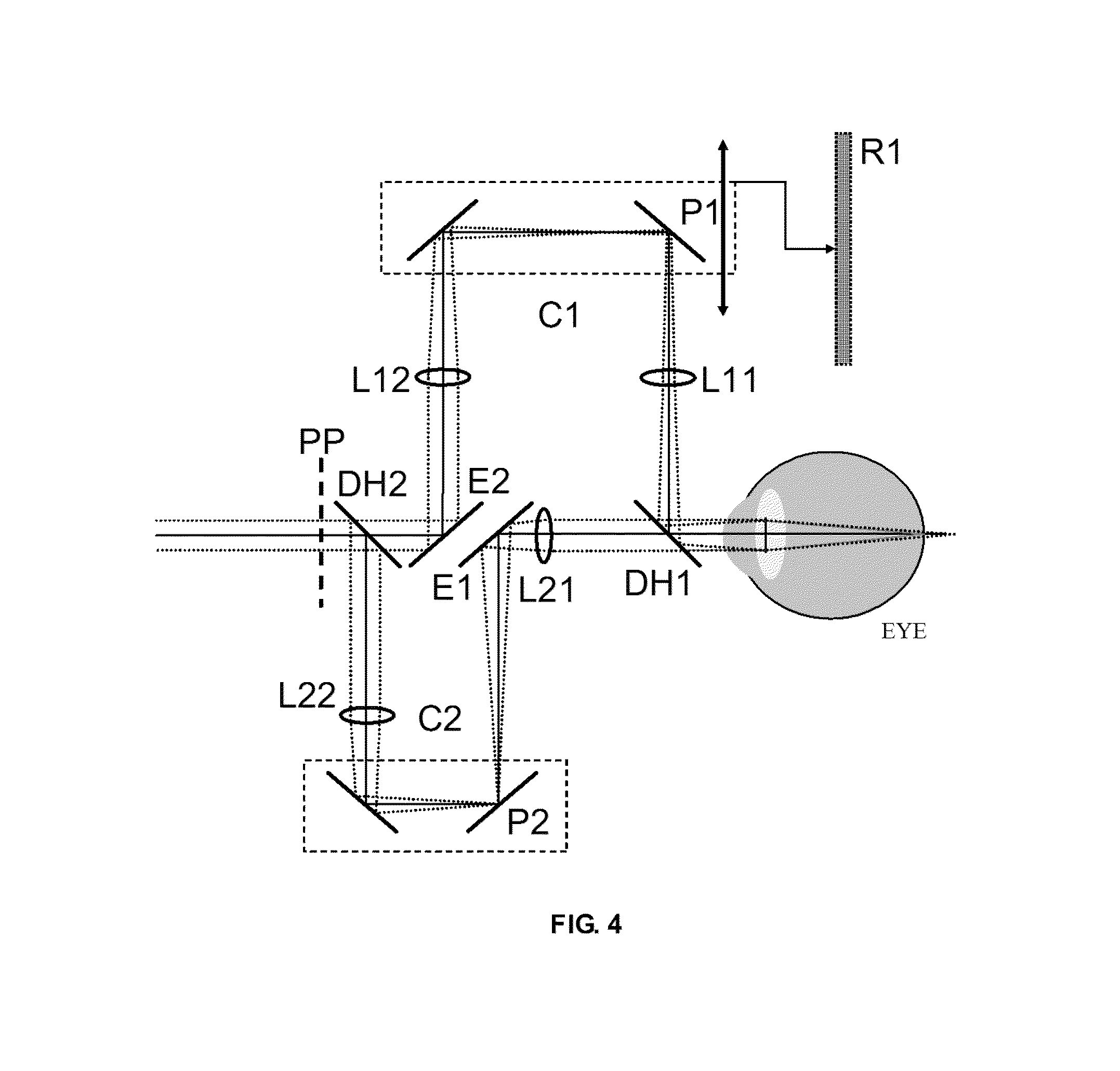
[0016]FIG. 1 shows a simple scheme of the operation of the invention, based on a purely optical system that includes only mirrors, beam splitters and lenses with spherical surfaces, without needing software for computation or processing images, nor display elements, active or aspheric optical elements, providing compactness, simplicity and low cost thereto. The instrument comprises two observation channels, one corresponding to distant vision and another for near vision, providing the eye different vergences (optical power). In the scheme, the upper channel induces “n” diopters and the lower one “m” diopters. As in the invention described in U.S. Pat. Nos. 7,131,727 and 7,455,403, one of the keys for the proper operation of the present invention is that the eye is able to simultaneously observe objects by both optical channels, and that the optical axes at the output channel match exactly, such that two perfectly superimposed and simultaneous imag...
PUM
 Abstract
Description
Claims
Application Information