This helps you quickly interpret patents by identifying the three key elements:
Problems solved by technology
Method used
Benefits of technology
Benefits of technology
The patent text describes the advantages of separate manufacturing of the rotor body and shaft. This includes less material loss during production, the ability to use different materials based on mechanical and thermal load requirements, the ability to repair or replace individual parts instead of the entire rotor, the use of tension elements to keep the stretch element under pre-stress, and the option of using ceramic or glass materials for higher resistance to temperature and low expansion coefficients.
Problems solved by technology
Leakage losses involve a reduction of the efficiency of the screw compressor.
A drawback of this is that material is lost during production.
Another drawback of such single part rotors is that the entire rotor, i.e., both the rotor body and the journals, must be manufactured from the same material.
However, different parts of the rotor pose different requirements to the material to be used.
It is practically impossible to use the journal itself as an inner ring of a bearing.
However, it is not evident to manufacture the entire rotor from such a special type of steel due to reasons of a more difficult processing of such material and the costs involved therein.
Another drawback of a single-piece rotor is that it is difficult to provide a suitable cooling channel therein.
Indeed, the dimensions of the cooling channel may not result in a substantial weakening of the structure.
This results in the distance between the cooling channel introduced and the outer surface of the rotor becoming too large to obtain efficient cooling.
Yet another drawback is that it is difficult or even impossible to repair a rotor when only a single part, such as the journal or the rotor body, is damaged.
It is also disadvantageous that placing sensors in the rotor, for example for measuring vibrations or temperature, is difficult.
Method used
Image
Click on the blue label to locate the original text in one second.
Reading with bidirectional positioning of images and text.
Examples
first embodiment
[0086]Though in this case, the nut, which forms the second tension element 12 in FIGS. 1 and 2, is integrated in the rotor body 2.
[0087]To that end, an inner screw thread 22 is provided in the rotor body 2 at the height of the end plane 10. In assembled condition of The rotor 1 according to the invention, this inner thread 22 cooperates with the outer screw thread 17 on the shaft 6.
[0088]In this case, besides to the thread 22, an inner edge 23 is provided in the wall of the passage 5.
[0089]In the example shown, a bush-shaped part 24 is placed at the end side 10 of the rotor body 2, in the prolongation of the central passage 5, although the presence of said bush-shaped part 24 is not strictly necessary according to the invention.
[0090]The method of manufacturing a rotor 1 according to this embodiment is also very easy and similar to the method of the first embodiment.
[0091]The shaft 6 is passed through the continuous central passage 5, applied in the rotor body 2, with the journal 4,...
third embodiment
[0096]Also in this third embodiment, the rotor body 2 is provided with an approximately central axial passage 5 through which the shaft 6 can be introduced.
[0097]To that end, and if desired, recesses 14 and 21 are made in the end planes 9 and 10 of the rotor body 2.
[0098]In this case, the shaft 6 is made as a composite component, consisting of the journals 3 and 4 and a stretch element 7.
[0099]The journals 3 and 4 are preferably made as cylindrical-shaped parts.
[0100]These journals 3 and 4 have at their end planes 25 and 26 a diameter D1 which is somewhat smaller than the diameter d of the continuous central passage 5.
[0101]Central, non-through bored holes 27, or so-called blind holes, are made in these end planes 25 and 26. Eventually, these bored holes 27 have an inner screw thread 28. These bored holes 27 may be made as through bored holes such that these could extend through respectively, journal 3 or 4.
[0102]Collars 29, which can also be made as raised edges, are located on the...
PUM
Property
Measurement
Unit
Fraction
aaaaa
aaaaa
Fraction
aaaaa
aaaaa
Force
aaaaa
aaaaa
Abstract
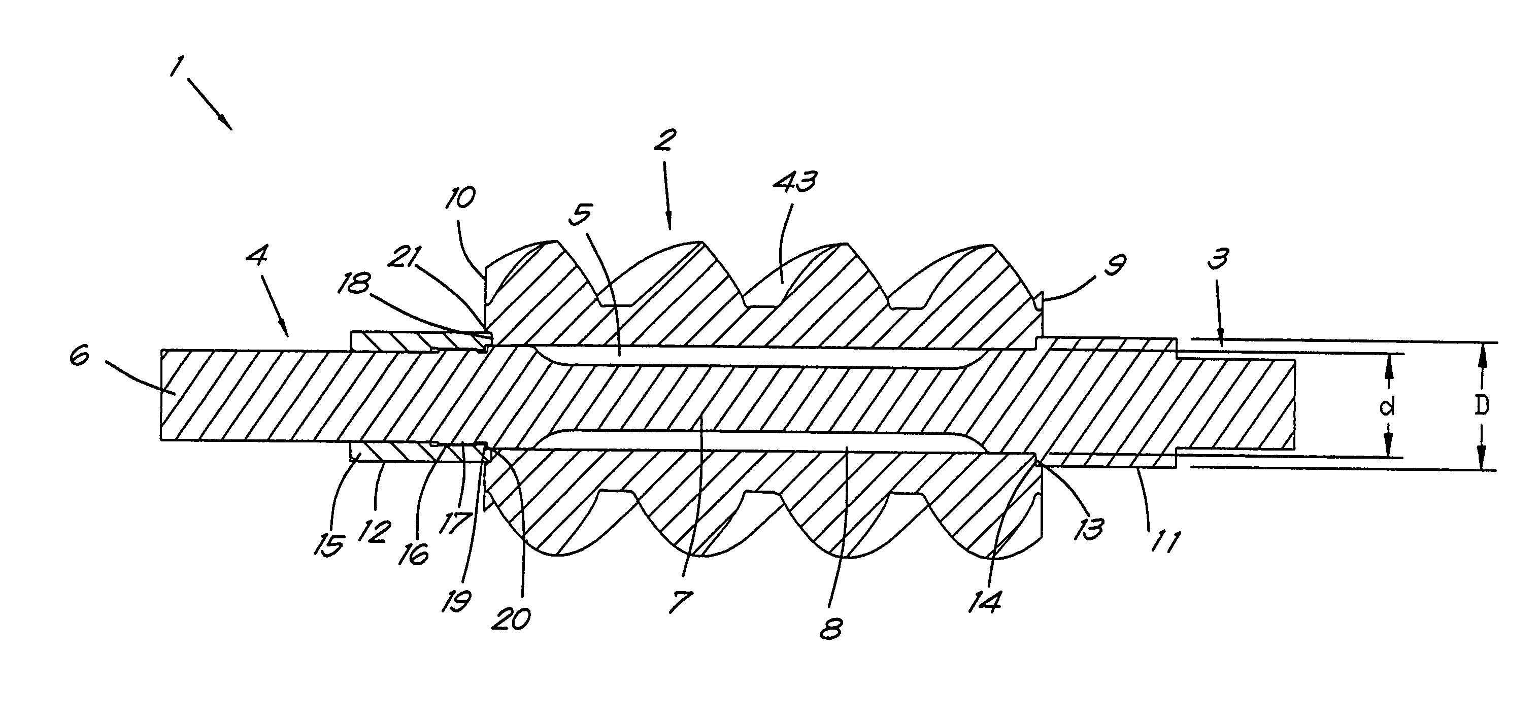
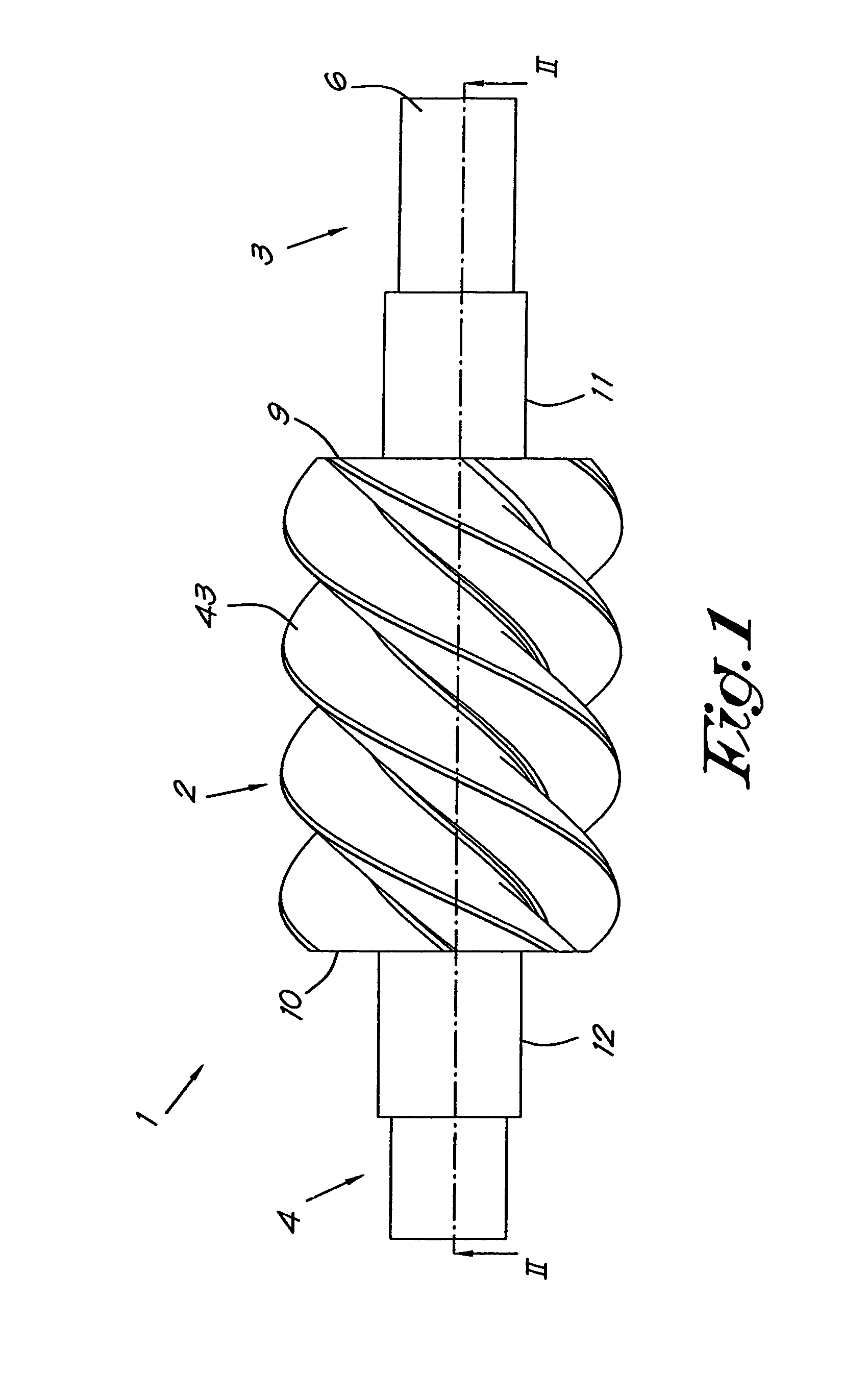
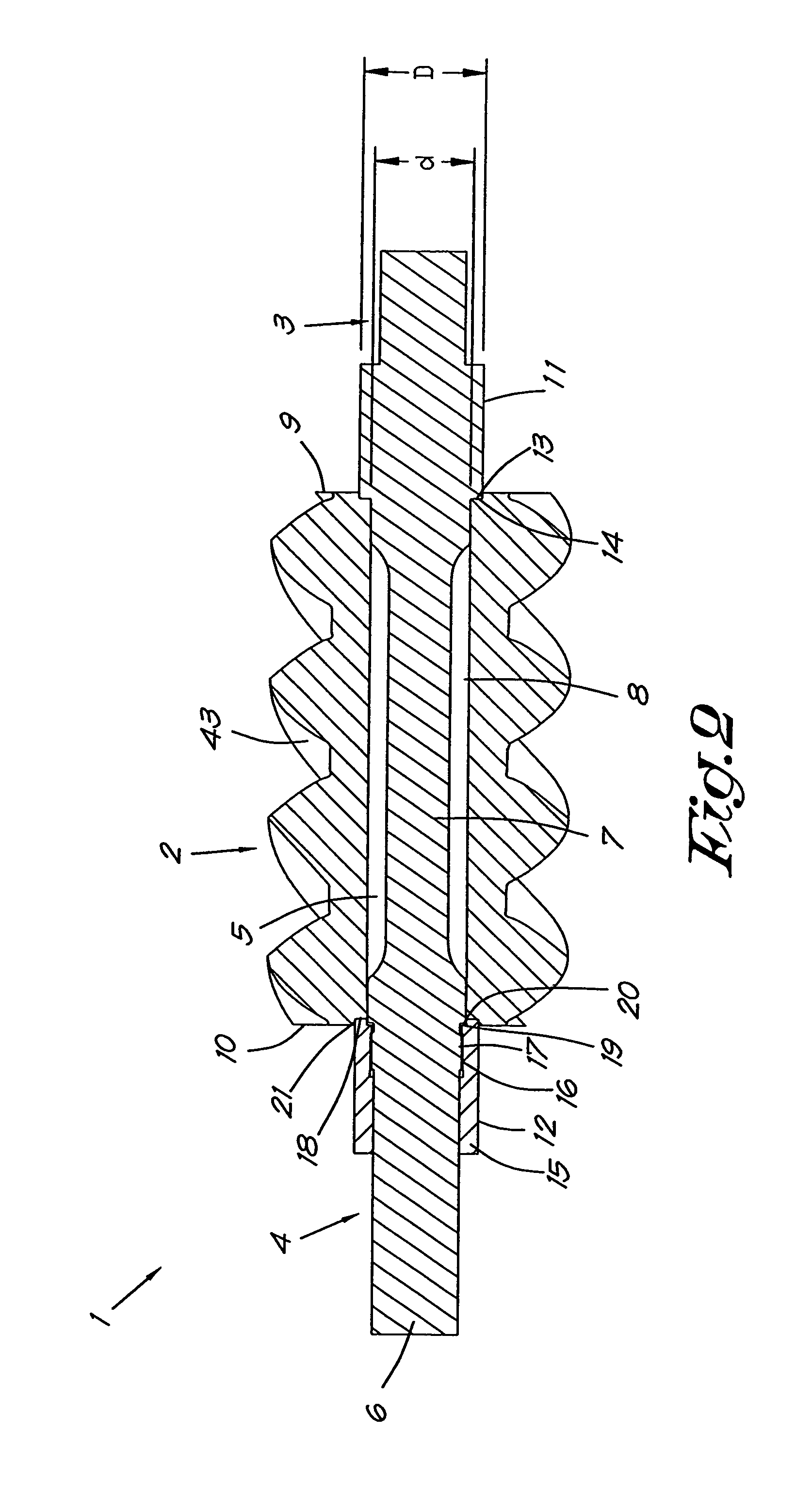
Rotor for a screw compressor includes a rotor body (2) and a shaft (6), whereby said shaft extends at least with a part into or through a central or approximately central axial bored hole or passage (5) in the rotor body (2). The shaft (6) has a stretch element (7), whereby the rotor body (2) or at least a part thereof is held on the shaft (6) by means of tension elements (11 and 12) which are locked or can be locked axially with respect to the shaft and which are connected with each other by means of the stretch element (7). During the mounting of the rotor body (2) on the shaft (6), the stretch element is pre-tensioned by means of a tensile load and after locking the tension elements (11 and 12) and removal of the tensile load, is kept under an axial pretension which, in case the rotor (1) is not built in, amounts to at least thirty percent of the yield strength of the material of the stretch element (7), and this by means of the tension elements (11 and 12) which are kept apart from each other by the rotor body (2) or a part thereof.
Description
BACKGROUND OF THE INVENTION[0001]1. Field of the Invention[0002]The present invention relates to a rotor for a screw compressor.[0003]2. Related Art[0004]As is known, a screw compressor is equipped with a drive, typically in the shape of a motor, and with a screw compressor element comprising a casing having therein two meshing rotors, whereby one of said rotors, whether or not through a transmission, is driven by the aforementioned drive.[0005]Due to the meshing of the rotors, during the operation of the screw compressor, a fluid, such as air, is sucked in at the inlet of the screw compressor element, which fluid is then compressed between both rotors and is finally expelled at the outlet side of the compressor element under a certain outlet pressure.[0006]The meshing screw shaped parts of the rotors are referred to as the rotor bodies. As is known, one of the rotors has the shape of a male rotor with lobes, while the other rotor has the shape of a female rotor with grooves, in whi...
Claims
Application Information
Patent Timeline
Application Date:The date an application was filed.
Publication Date:The date a patent or application was officially published.
First Publication Date:The earliest publication date of a patent with the same application number.
Issue Date:Publication date of the patent grant document.
PCT Entry Date:The Entry date of PCT National Phase.
Estimated Expiry Date:The statutory expiry date of a patent right according to the Patent Law, and it is the longest term of protection that the patent right can achieve without the termination of the patent right due to other reasons(Term extension factor has been taken into account ).
Invalid Date:Actual expiry date is based on effective date or publication date of legal transaction data of invalid patent.

