Reflective optical components for lithographic apparatus and device manufacturing method

a technology of lithographic apparatus and optical components, which is applied in the direction of printers, nanotechnology, radiation therapy, etc., can solve the problems of ruthenium being relatively easily contaminated with sulphur, reducing the reflectivity of reflective coatings, and loss of reflectivity for euv radiation, etc., to achieve easy cleaning, device manufacturing, and not affecting the effect of lithographic apparatus

Inactive Publication Date: 2016-10-18
ASML NETHERLANDS BV
View PDF18 Cites 2 Cited by
  • Summary
  • Abstract
  • Description
  • Claims
  • Application Information

AI Technical Summary

Benefits of technology

[0010]The ruthenium cap layer is useful as a protective layer which is easily cleaned to remove deposits which build up during use of EUV lithography apparatus, and is resistant to oxide formation, and does not lead to excessive loss in reflectivity for EUV. However, it has been found that ruthenium is relatively easily contaminated with sulphur from sulphur compounds present as contaminants during use of the lithography apparatus or present as contaminants during the in-situ cleaning processes. This leads to a build up of sulfur or sulfur compounds on the reflective surfaces, eventually leading to loss in reflectivity for EUV radiation. Contaminants may originate, for instance, from resist, from materials used, and partly from environmental air to which reflective surfaces may be exposed during maintenance activity.
[0011]It is desirable to provide protective layers for EUV reflective surfaces which maintain EUV reflectivity in the presence of sulfur compound contaminants, and / or from which sulfur or sulfur compounds may be easily cleaned.
[0012]It is an aspect of embodiments of the invention, amongst others, to provide a protective cap layer for reflective EUV optical components for use in lithography apparatus which reduces sulfur contamination without substantial loss of EUV reflectance.
[0020]According to an aspect of the invention, there is provided the use of a bimetal cap layer comprising a first metal and second metal, different from the first metal, as a coating on optical components arranged to reflect EUV in a lithographic apparatus, to reduce loss of EUV reflectivity of the optical components arising from deposition of sulfur-containing contaminants.
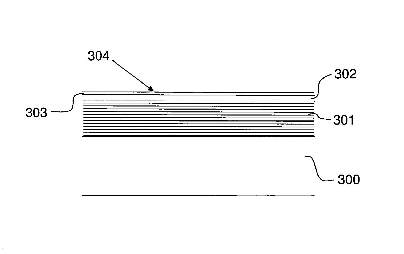
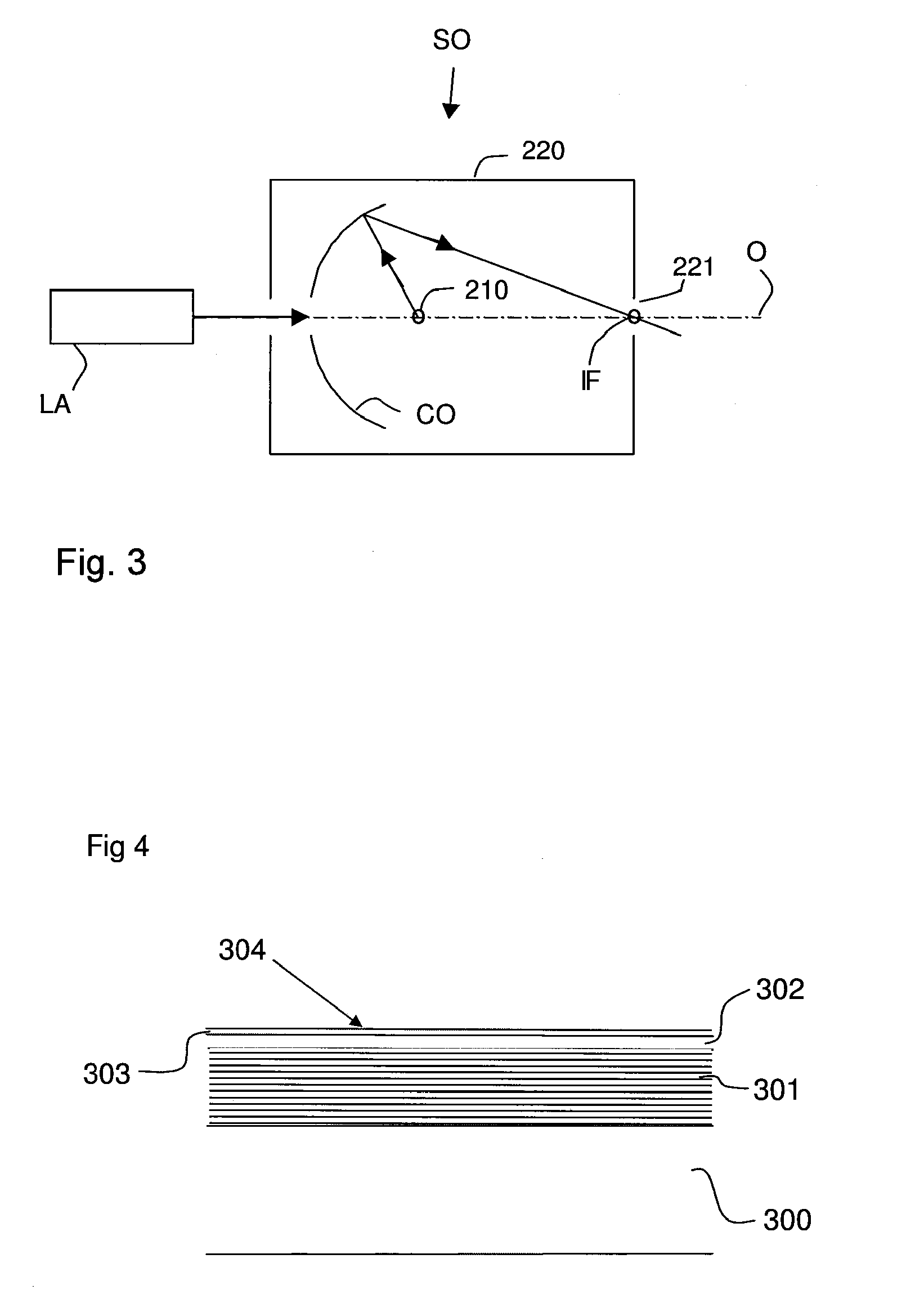
[0027]The reflective layer suitably comprises alternating layers of molybdenum, or diamond-like carbon, and silicon, arranged to provide high reflectivity for EUV radiation.

Problems solved by technology

The metal top layer is used to prevent oxidation, but may give rise to a decrease in reflectivity of the reflective coating.
However, it has been found that ruthenium is relatively easily contaminated with sulphur from sulphur compounds present as contaminants during use of the lithography apparatus or present as contaminants during the in-situ cleaning processes.
This leads to a build up of sulfur or sulfur compounds on the reflective surfaces, eventually leading to loss in reflectivity for EUV radiation.

Method used


Image

  • Reflective optical components for lithographic apparatus and device manufacturing method
  • Reflective optical components for lithographic apparatus and device manufacturing method
  • Reflective optical components for lithographic apparatus and device manufacturing method

Examples


Embodiment Construction

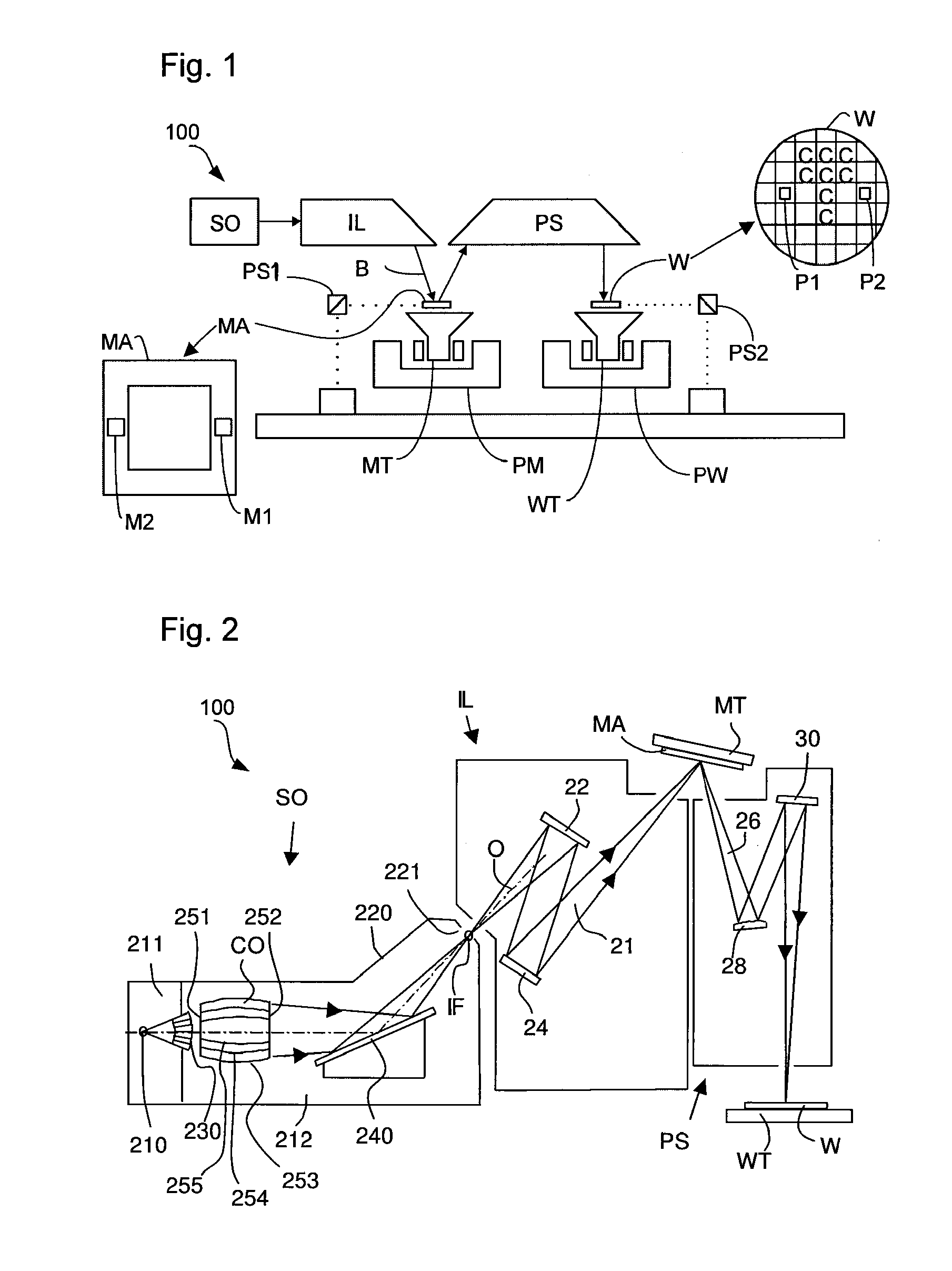
[0034]FIG. 1 schematically depicts a lithographic apparatus 100, including a source collector module SO, according to one embodiment of the invention. The apparatus comprises: an illumination system (illuminator) IL configured to condition a radiation beam B, for instance of EUV radiation; a support structure (e.g. a mask table) MT constructed to support a patterning device (e.g. a mask or a reticle) MA and connected to a first positioner PM configured to accurately position the patterning device; a substrate table (e.g. a wafer table) WT constructed to hold a substrate (e.g. a resist-coated wafer) W and connected to a second positioner PW configured to accurately position the substrate; and a projection system (e.g. a reflective projection system) PS configured to project a pattern imparted to the radiation beam B by patterning device MA onto a target portion C (e.g. comprising one or more dies) of the substrate W.

[0035]The illumination system may include various types of optical c...


PUM

PropertyMeasurementUnit
thicknessaaaaaaaaaa
wavelengthaaaaaaaaaa

Abstract

A reflective optical component is configured to reflect EUV radiation. The reflective optical component has a reflective layer with a bimetal cap layer of differing first and second metals selected to ensure that the outer surface of the cap layer is substantially unreactive or non-adsorptive to sulfur. The bimetal cap layer may be an alloy of the two metals or may consist of a base layer of the first metal deposited on the reflective layer and a surface layer of the second metal on the base layer. The interaction of the two metals may lead to modification of the bonding energy to the outer face of the cap layer of sulfur-containing molecules such as SO2 so that sulfur adsorption, which leads to loss of reflectivity, is reduced or eliminated.

Description

CROSS-REFERENCE TO RELATED APPLICATIONS[0001]This application claims the benefit of priority from U.S. Provisional Patent Application No. 61 / 436,303, filed Jan. 26, 2011, the entire content of which is incorporated herein by reference.FIELD[0002]The present invention relates to reflective optical components for a lithographic apparatus for device manufacture, particularly to reflective optical components suitable for reflecting extreme ultraviolet (EUV) radiation for use in device lithography.BACKGROUND[0003]A lithographic apparatus is a machine that applies a desired pattern onto a substrate, usually onto a target portion of the substrate. A lithographic apparatus can be used, for example, in the manufacture of integrated circuits (ICs). In that instance, a patterning device, which is alternatively referred to as a mask or a reticle, may be used to generate a circuit pattern to be formed on an individual layer of the IC. This pattern can be transferred onto a target portion (e.g. c...

Claims


Application Information

Patent Timeline
Patent Type & Authority Patents(United States)
IPC IPC(8): G03B27/54G21K1/06B82Y10/00G03F7/20G02B5/08
CPCG21K1/062B82Y10/00G02B5/0891G03F7/70316G03F7/70958
Inventor SILOVA, MARIANNA YURYEVNA
Owner ASML NETHERLANDS BV
Why Eureka
Try Eureka