

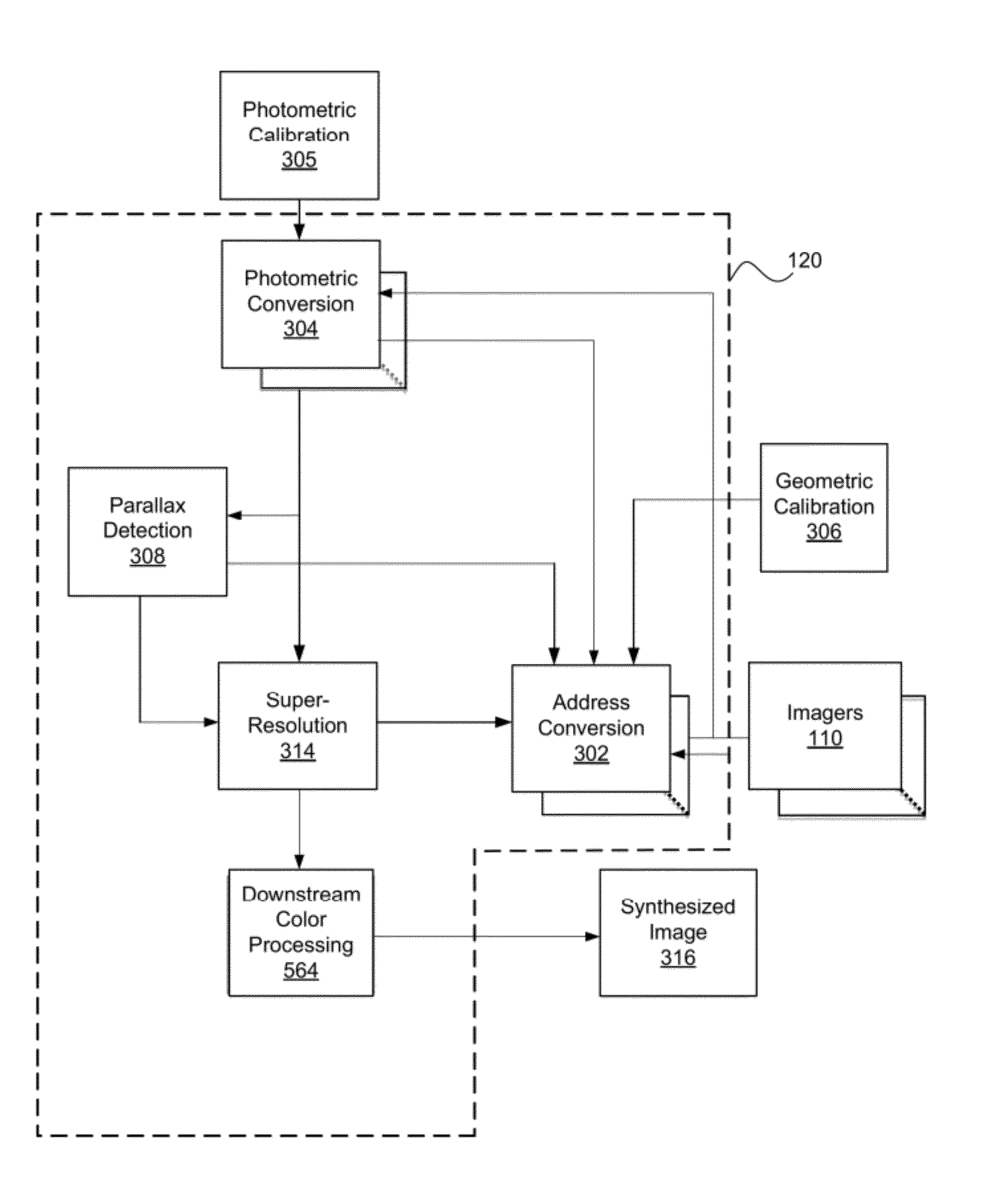
Systems and methods for synthesizing high resolution images using super-resolution processes
a high-resolution image and process technology, applied in the field of imaging, can solve the problems of significantly affecting the overall form factor of the mobile device, image sensors are subject to various performance constraints, etc., and achieve the effect of improving the recovery of high frequency information, improving the objective and subjective quality of the obtained super-resolution imag
- Summary
- Abstract
- Description
- Claims
- Application Information
AI Technical Summary
Benefits of technology
Problems solved by technology
Method used
Image

Examples
case b
[0266 can be defined as the situation where the pixel (k,l) at a decimation position does not fall within Case A above. The difference from Case A above comes from how the gradient is computed at these types of positions (k,l). To determine the gradient at such positions two types of information can be determined:
[0267]1) the LR imagers to select for determining gradient at (k,l), and
[0268]2) the coordinates to consider in the selected LR imagers.
[0269]To decide on the first question, a window is centered at position (k,l) in the warped and blurred HR image estimate, the neighboring pixel positions in that window are checked for certain characteristics, and their information is recorded according to several criteria. These include whether a neighboring pixel was warped from a Type 1 or Type 2 pixel position in the current HR estimate, as previously defined, and whether the source LR imager from which the pixel originates is in the same color channel as the reference LR imager. If a ...
PUM
 Abstract
Description
Claims
Application Information