Adapterless closure assembly for composite pressure vessels

a technology of pressure vessel and assembly, applied in the direction of cable termination, manufacturing tools, container discharging methods, etc., can solve the problems of complex construction and sealing abilities, and achieve the effect of effective sealing capabilities and simplified construction

Active Publication Date: 2014-11-11
QUANTUM FUEL SYSTEMS LLC
View PDF36 Cites 18 Cited by
  • Summary
  • Abstract
  • Description
  • Claims
  • Application Information

AI Technical Summary

Benefits of technology

[0007]It is an object of the present invention is to provide an improved polar boss assembly for us...

Problems solved by technology

This can be disadvantageous as the seal surface of the liner has tight tolerances, and several steps are required to complete the assembly.
In addition, in certain of these c...

Method used


Image

  • Adapterless closure assembly for composite pressure vessels
  • Adapterless closure assembly for composite pressure vessels
  • Adapterless closure assembly for composite pressure vessels

Examples


Embodiment Construction

[0017]The following detailed description is of the best presently contemplated modes of carrying out the invention. This description is not to be taken in a limiting sense, but is made merely for the purpose of illustrating general principles of embodiments of the invention. The scope of the invention is best defined by the appended claims.

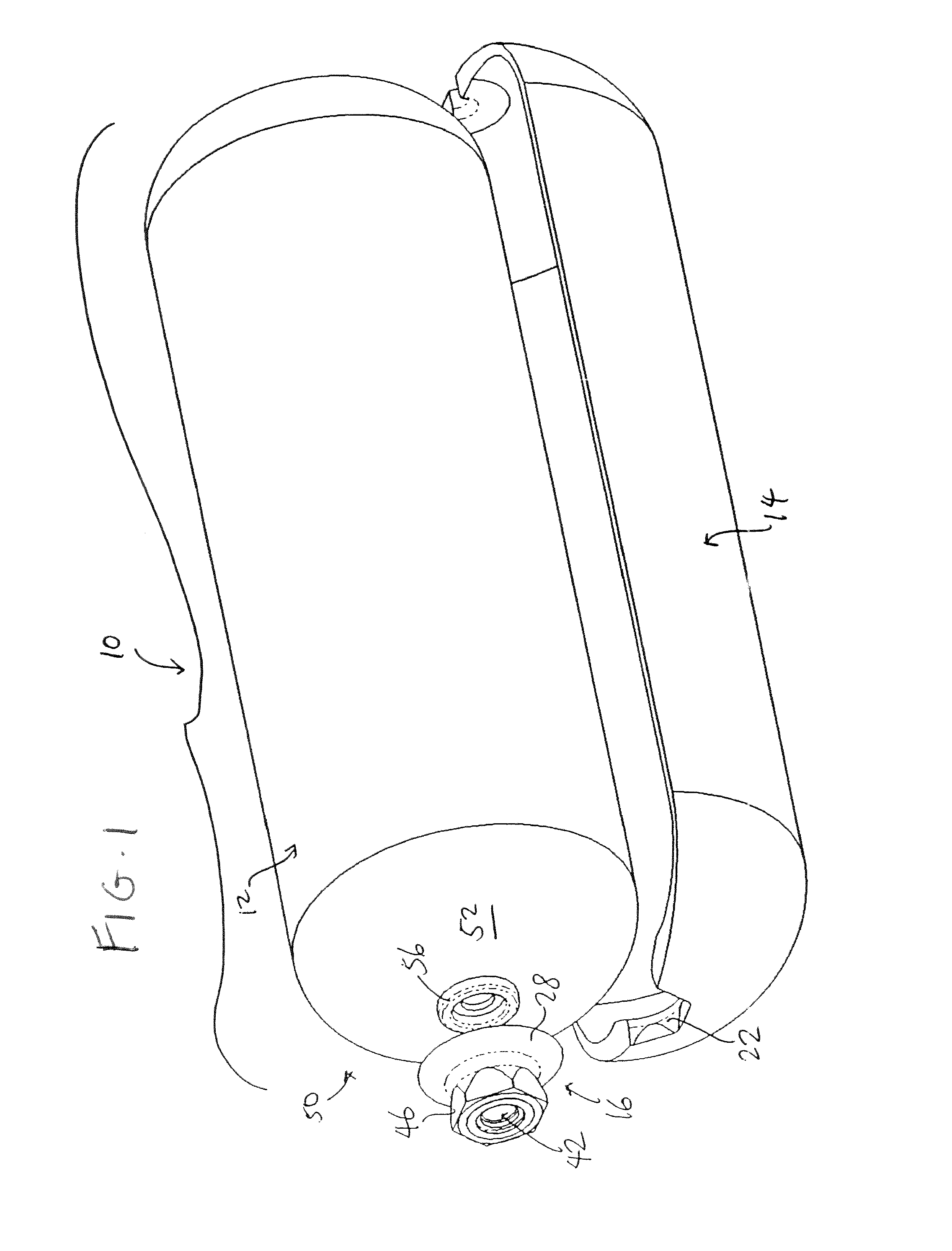
[0018]FIG. 1 illustrates a pressure vessel 10 according to the present invention. The pressure vessel 10 includes a liner 12 and an outer shell 14 that is formed by wrapping composite fibers and epoxy resin. Even though FIG. 1 shows half of the outer shell 12, it will be appreciated by one skilled in the art that the outer shell 12 extends completely around the liner 12. The construction and assembly of the liner 12 and the outer shell 14 are well-known in the art and shall not be described further herein.

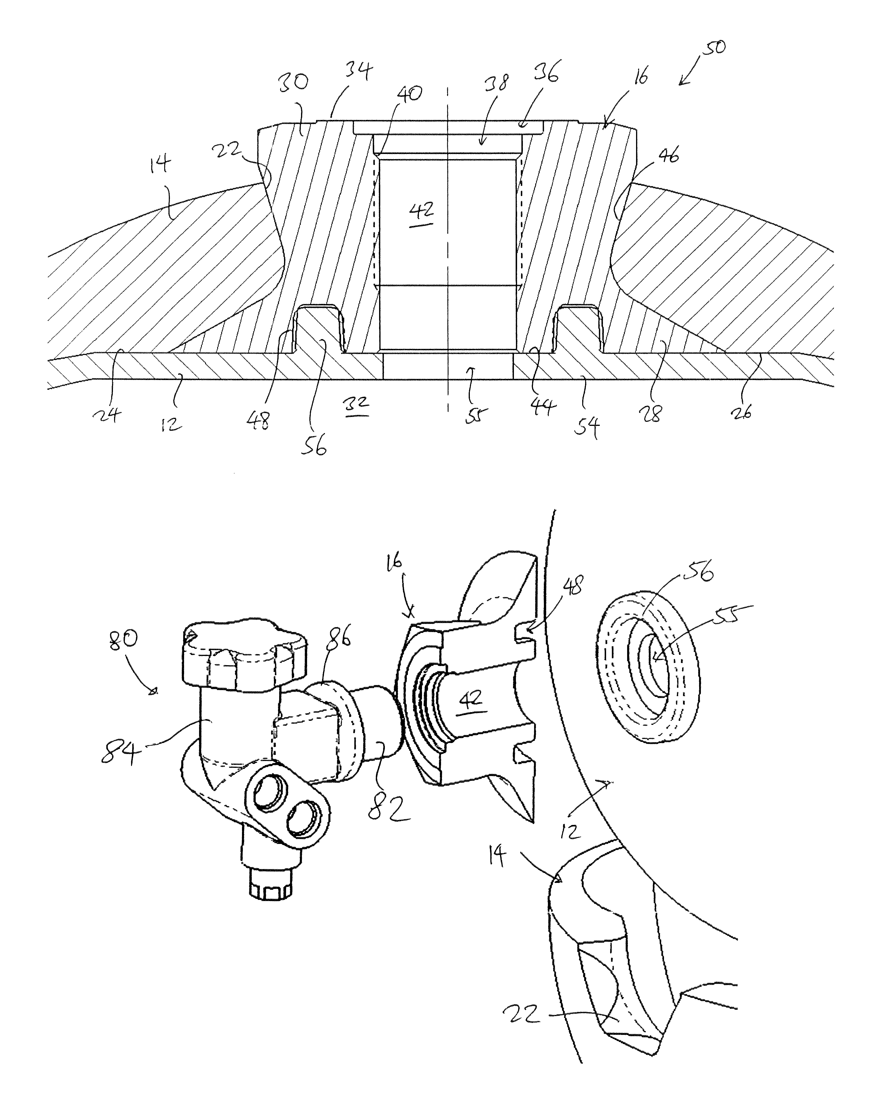
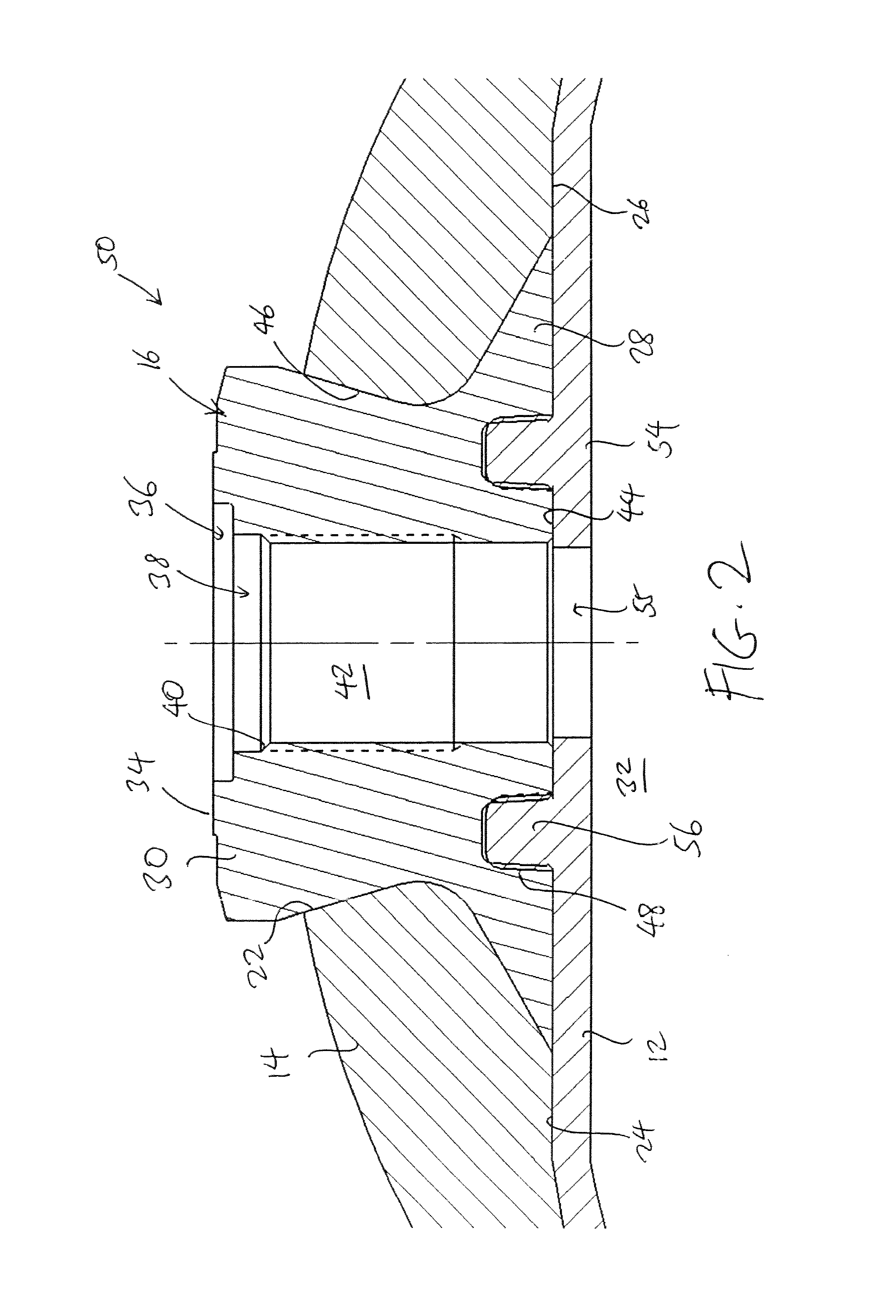
[0019]FIG. 2 is a cut-away view of an end portion 50 of the pressure vessel 10 showing the closure assembly, which includes a polar boss 16. An ...


PUM

PropertyMeasurementUnit
Angleaaaaaaaaaa
Metallic bondaaaaaaaaaa

Abstract

A pressurized-gas storage assembly has a liner defining a gas storage chamber and an end portion with a planar surface, with an access opening on the planar surface that is in fluid communication with the gas storage chamber. A raised circular ring extends from the planar surface and surrounds the access opening. The assembly also includes a polar boss having a longitudinally extending part that has a top surface with a recessed opening, and a planar bottom surface, with a channel extending through the polar boss to serve as a passageway through the polar boss. A circular groove is provided on the bottom flat surface of the polar boss, with the raised ring received inside the circular groove. An outer shell is provided around the entirety of the liner, with the outer shell having an edge-defining aperture that receives the polar boss.

Description

BACKGROUND OF THE INVENTION[0001]1. Field of the Invention[0002]This invention relates to storage tanks having liners, especially storage tanks with plastic liners used for storing compressed gaseous fuels. In particular, the present invention is related to a closure assembly for a pressure vessel, which is also a term used to describe such storage tanks.[0003]2. Description of the Prior Art[0004]Pressure vessels are widely used to store liquids and gases under pressure. One growing application of pressure vessels is their use in the storage of alternative fuels, such as natural gas, hydrogen or propane, for use in vehicles such as automobiles. Natural gas and propane are increasingly viewed as preferable to gasoline for fueling vehicles. Accordingly, approaches have been devised for converting gasoline-fueled vehicles to natural gas-fueled or propane-fueled vehicles by retrofitting them to use natural gas or propane instead of gasoline. Additionally, new vehicles are currently bein...

Claims


Application Information

Patent Timeline
IPC IPC(8): F17C1/00B65D25/14
CPCF17C2205/037F17C1/005B65D25/14F17C2209/234F17C2209/21B23P19/04F17C2209/22F17C2203/0634F17C2205/0305F17C1/00F17C2203/0636F17C2203/0663F17C2205/0382F17C2205/0394F17C2209/227F17C2221/011F17C2221/033F17C2221/035F17C2223/0123F17C2223/036F17C2270/0171F17C2270/0178F17C2270/0781F17C2270/079Y10T29/49826Y10T29/49881Y10T29/49904F17C2201/0109F17C2203/0604F17C1/06F17C13/002F17C2203/0673F17C2209/2109F17C2260/011F17C2260/036
Inventor WARNER, MARKLEAVITT, MARK
Owner QUANTUM FUEL SYSTEMS LLC
Why Eureka
Try Eureka