Rotary cutting tool having PCD cutting tip

a cutting tip and rotary cutting technology, applied in the field of cutting tools, can solve the problems of reducing strength, difficulty in cutting through-coolant holes in the flank of drills, and high cost of edm process, and achieve the effect of improving the design of coolant holes

Active Publication Date: 2014-11-11
KENNAMETAL INC
View PDF16 Cites 12 Cited by
  • Summary
  • Abstract
  • Description
  • Claims
  • Application Information

AI Technical Summary

Benefits of technology

[0029]It is to be appreciated that the present invention provides a number of benefits over known PCD drills. Such benefits include, for example, without limitation, the ability to use existing coolant hole rods in manufacturing PCD drills, does not require a central coolant hole (thus stronger), eliminates any need for EDM, requires less processing time (thus lower costs), and the differential helix can be readily adjusted to produce favorable dynamic behavior.

Problems solved by technology

As veined PCD drills are commonly fabricated as a PCD nib and rod which are later brazed together, it is difficult to have through-coolant holes breaking out in the flank of the drill.
Such EDM process is typically quite expensive due to necessary set-up and processing times. Additionally, known veined PCD drills commonly utilize a central coolant hole through the core of the drill which feeds the coolant holes formed in the nib via EDM.
The presence of such a central coolant hole generally reduces the strength, and thus the durability of the drill, a critical aspect for drills used to drill titanium materials.

Method used


Image

  • Rotary cutting tool having PCD cutting tip
  • Rotary cutting tool having PCD cutting tip

Examples


Embodiment Construction

[0020]Directional phrases used herein, such as, for example, left, right, front, back, top, bottom and derivatives thereof, relate to the orientation of the elements shown in the drawings and are not limiting upon the claims unless expressly recited therein. Identical parts are provided with the same reference number in all drawings.

[0021]As used herein, the term “number” shall be used to refer to any non-zero quantity (i.e., one or any quantity greater than one).

[0022]As used herein, the term “about” shall be used to refer to a point near, or at, a particular identified point (i.e., proximate).

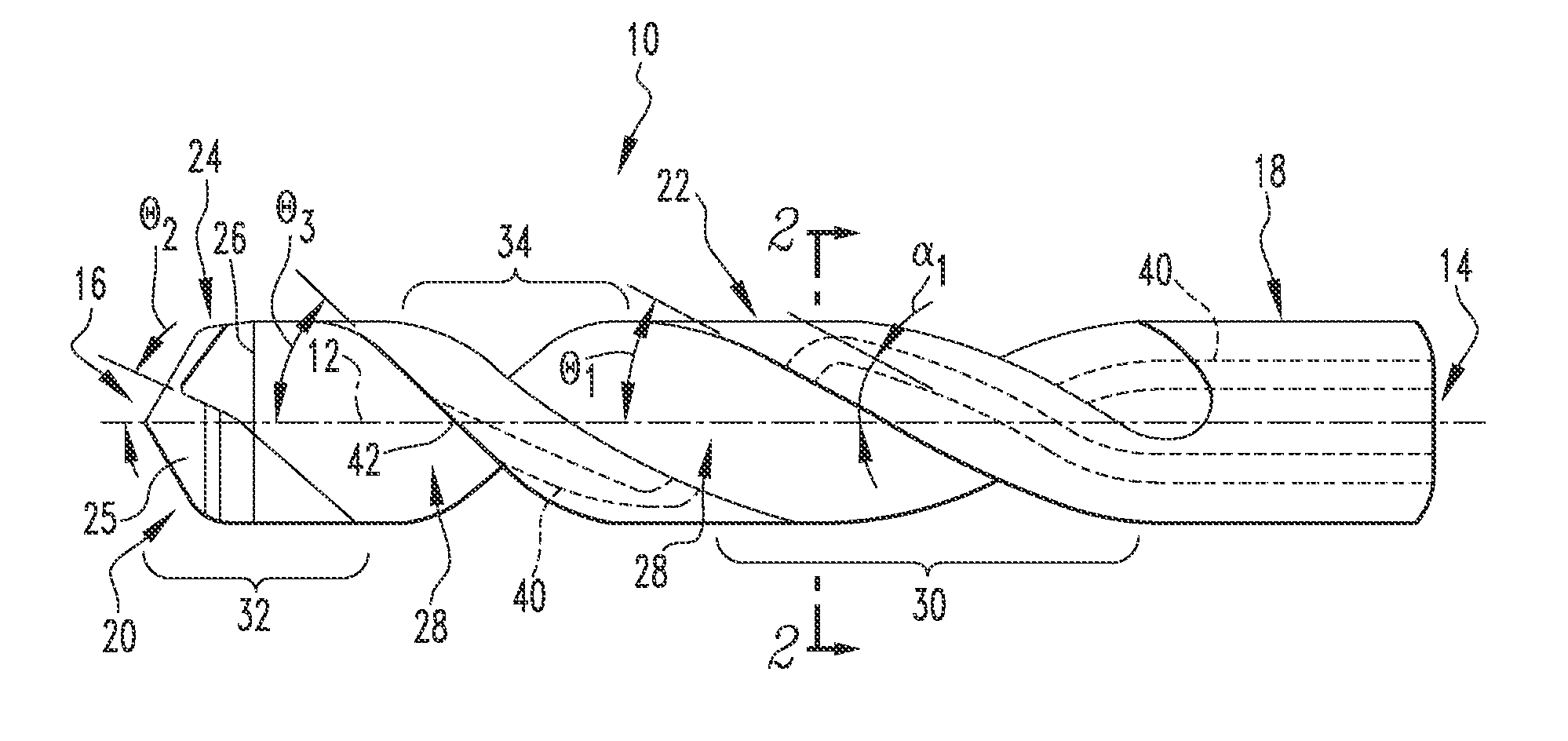
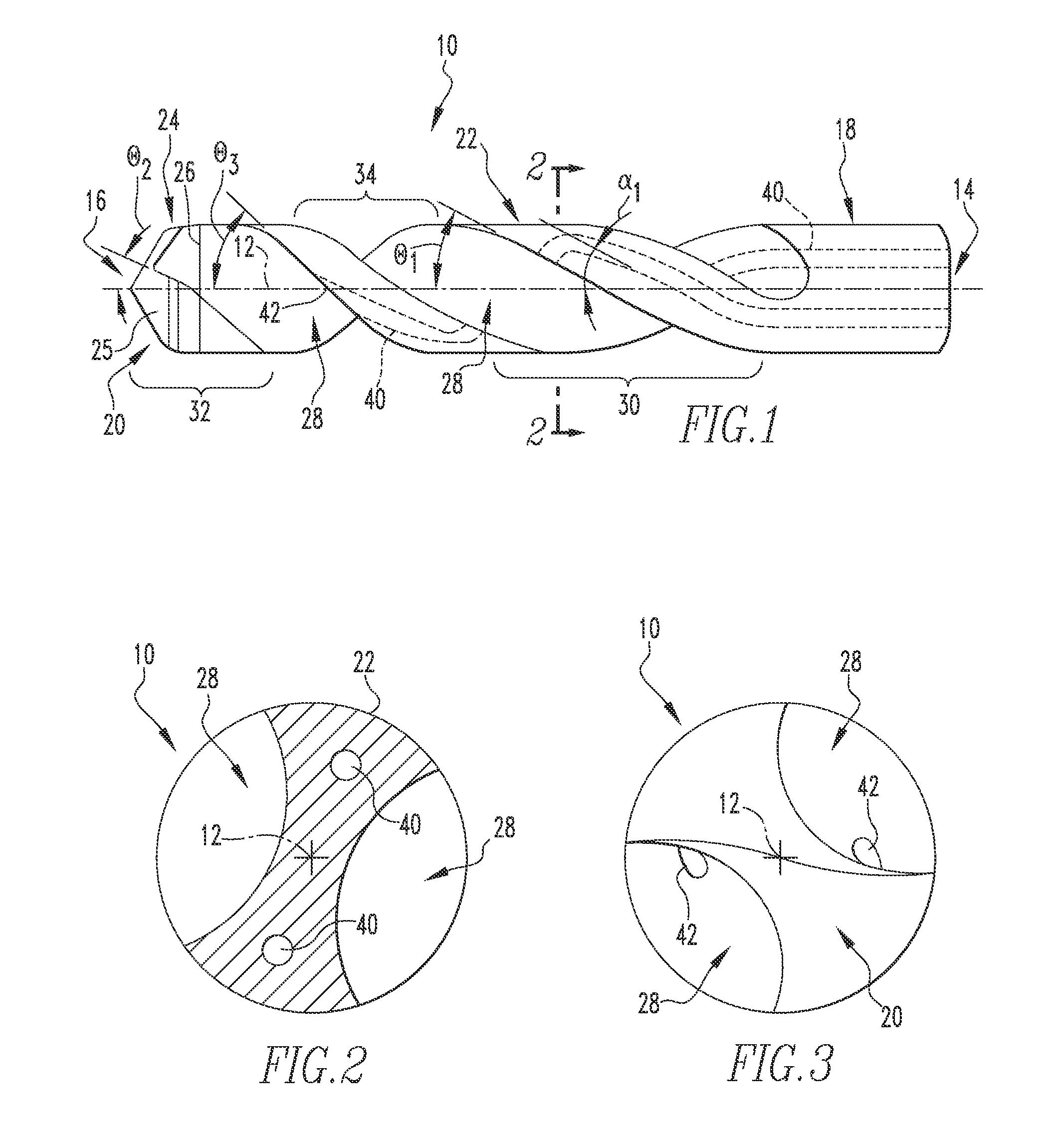
[0023]FIGS. 1-3 depict an example cutting tool 10, in accordance with a non-limiting embodiment of the present invention, for conducting cutting operations on a workpiece (not shown) when cutting tool 10 is rotated about a central longitudinal axis 12. Although depicted as a drill in the exemplary embodiment described herein, it is to be appreciated that concepts described herein are applicab...


PUM

PropertyMeasurementUnit
angleaaaaaaaaaa
helix angleaaaaaaaaaa

Abstract

A cutting tool for performing hole-cutting operations on a workpiece when the cutting tool is rotated about a central longitudinal axis includes a generally cylindrical body having a first end structured to be mounted to a machine tool and an opposite second end structured to engage and perform cutting operations on the workpiece. A number of coolant passages are defined in the generally cylindrical body, each coolant passage of the number of coolant passages is disposed at a first helix angle relative to the central longitudinal axis. A number of flutes are formed in the generally cylindrical body, each flute of the number of flutes includes a first portion at or about the first end of the generally cylindrical body, a second portion at or about the second end of the generally cylindrical body, and a transition portion disposed therebetween. The first portion of each flute is disposed generally at the first helix angle relative to the central longitudinal axis, the second portion of each flute is disposed generally at a second helix angle relative the central longitudinal axis, and the transition portion of each flute is disposed generally at a third helix angle relative to the central longitudinal axis greater than the first helix angle.

Description

BACKGROUND[0001]1. Field of the Invention[0002]The invention relates generally to rotary cutting tools and, more particularly, to cutting tools, such as drills, having polycrystalline-diamond (PCD) cutting tips. The invention further relates to a method for forming a cutting tool having a polycrystalline-diamond cutting tip.[0003]2. Background Information[0004]Polycrystalline-diamond (PCD) drills have historically been formed as straight fluted, facet point drills. More recently, veined PCD drills have been formed having helical flutes and more complex point geometries similar to solid carbide drills. One of the major uses of such highly engineered PCD drills is for drilling in composite materials, such as carbon fiber reinforced polymer (CFRP) titanium composites.[0005]Drilling in titanium requires good coolant flow within the drill to control the heat generated during drilling. As veined PCD drills are commonly fabricated as a PCD nib and rod which are later brazed together, it is...

Claims


Application Information

Patent Timeline
Patent Type & Authority Patents(United States)
IPC IPC(8): B23B51/06B23B51/02
CPCB23B2251/046B23B2226/315B23B2226/275B23B2222/88B23B51/02B23B51/06Y10T408/78B23P15/32B23B2240/08Y10T408/9097Y10T408/45B23B27/10B23B27/20B23C5/28
Inventor SAMPATH, KARTHIK
Owner KENNAMETAL INC
Why Eureka
Try Eureka