
Hydraulic machine, an energy conversion installation including such a machine, and the use of a hydrostatic labyrinth-bearing in such a machine

a technology of hydrostatic labyrinth and hydrostatic shaft, which is applied in the direction of propellers, propulsive elements, water-acting propulsive elements, etc., can solve the problems of increasing the cost of operating a prior art francis turbine, affecting the affecting the operation efficiency of the machine, so as to reduce the risk of water leakage, improve the technical and economical performance, and reduce the effect of water leakag

Inactive Publication Date: 2014-11-11
ALSTOM RENEWABLE TECH
View PDF22 Cites 0 Cited by
  • Summary
  • Abstract
  • Description
  • Claims
  • Application Information

AI Technical Summary

Benefits of technology

The invention proposes a new hydraulic machine that reduces leaks and increases efficiency. It isolates the first and second zones of the machine, minimizing leaks and allowing more water to drive the wheel in rotation. The bearing used in the machine has a small clearance, reducing water leakage. This design simplifies the manufacturing process and improves performance. Additionally, the invention provides an installation for converting hydraulic energy into electrical energy, offering improved technical and economical performance.

Problems solved by technology

Those various items of equipment, namely the labyrinth, the bearing, and the shaft seal, are relatively costly, and each of them requires regular maintenance, which further adds to the costs of operating a prior art Francis turbine.
Analogous problems arise with pumps, in particular with centrifugal pumps, and with turbine pumps.

Method used


Image

  • Hydraulic machine, an energy conversion installation including such a machine, and the use of a hydrostatic labyrinth-bearing in such a machine
  • Hydraulic machine, an energy conversion installation including such a machine, and the use of a hydrostatic labyrinth-bearing in such a machine
  • Hydraulic machine, an energy conversion installation including such a machine, and the use of a hydrostatic labyrinth-bearing in such a machine

Examples


Embodiment Construction

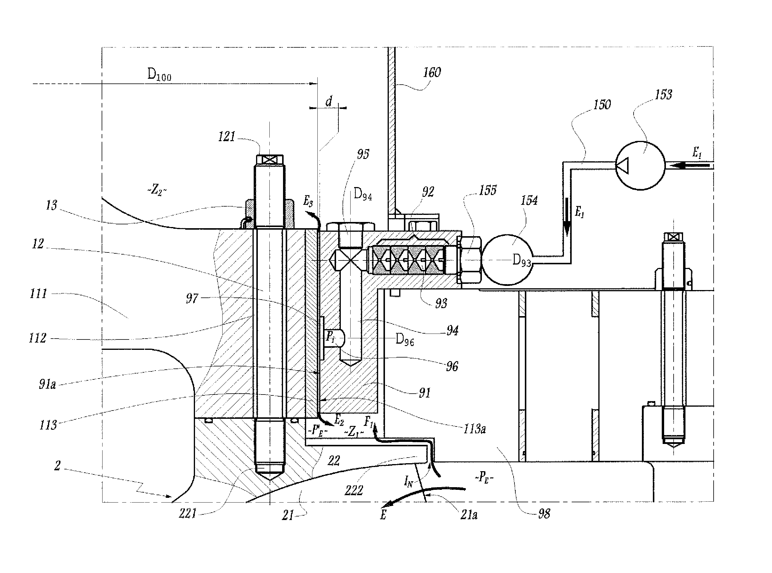
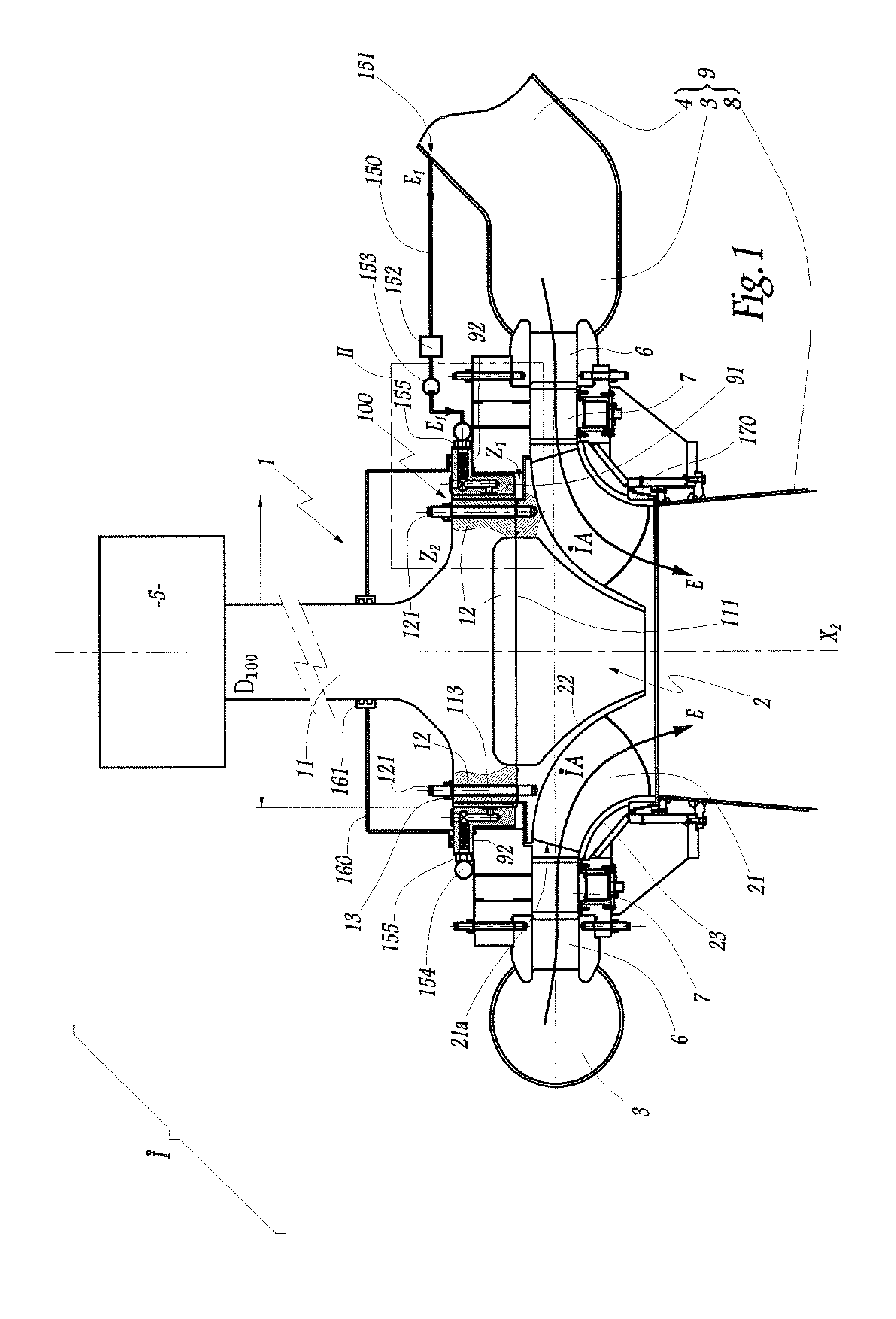
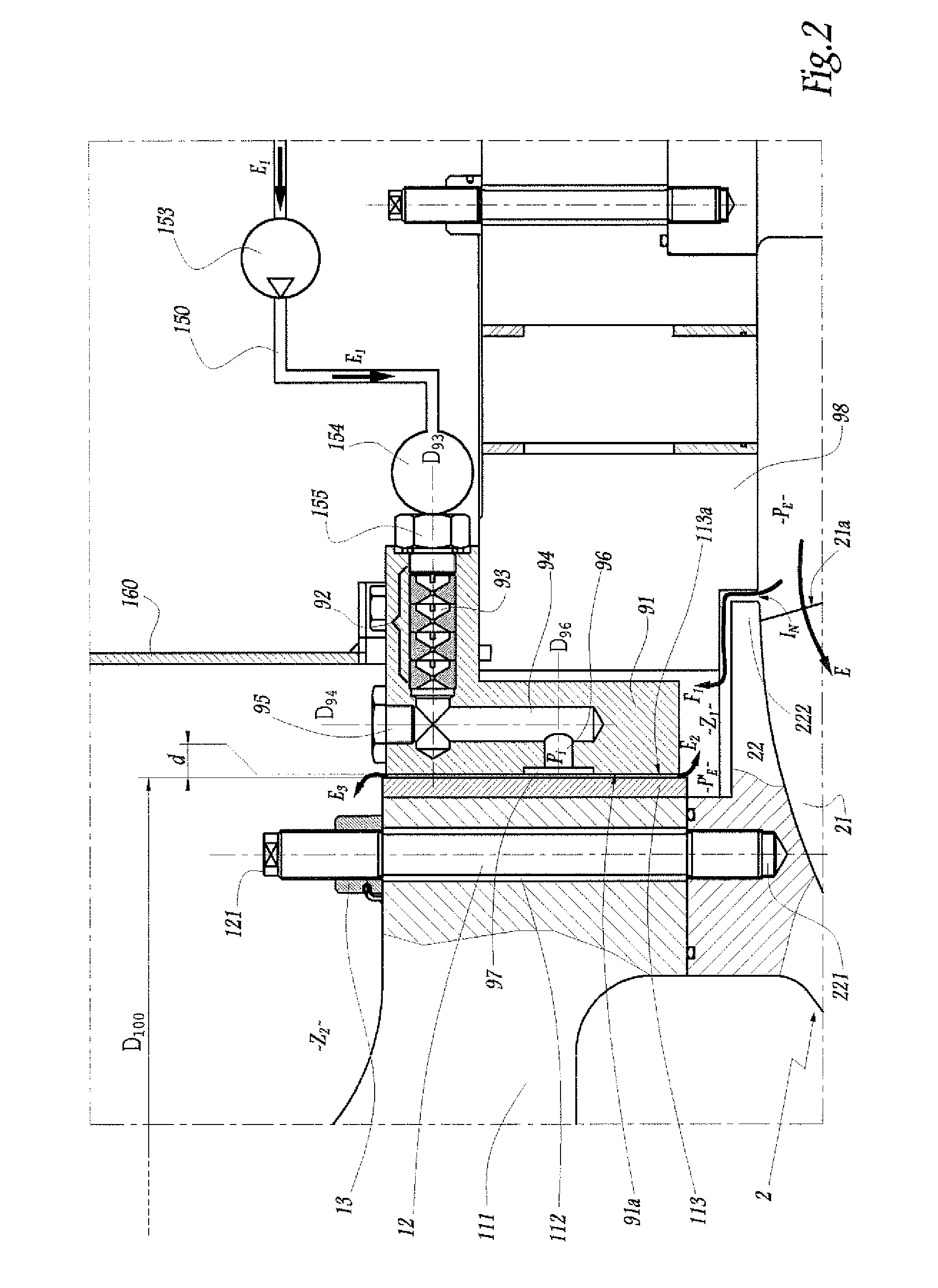
[0024]The installation shown in FIG. 1 includes a Francis turbine 1 whose wheel or “runner”2 is fed from a casing 3 into which a forced-flow duct 4 opens out. The turbine 1 is coupled via a shaft 11 to an alternator 5. Between the casing 3 and the wheel 2 there is disposed a series of stay vane blades 6 and of wicket gates 7 whose function is to guide a flow E that is coming from the duct 4 and from the casing 3 and that is to pass through the wheel 2 towards a discharge conduit 8.

[0025]The axis of rotation of the wheel is stationary and is referenced X2.

[0026]The wheel 2 is provided with blades 21 that extend between a ceiling 22 and a belt 23. The blades co-operate with one another and with the ceiling 22 and the belt 23 to define inter-blade spaces IA through which the flow E passes while it is flowing through the wheel 2.

[0027]The wheel 2 is fastened to the bottom end 111 of the shaft 11 by means of pins 12 that pass through orifices 112 provided in the end 111 and that are eng...


PUM


Abstract

This hydraulic machine (1) has a wheel (2) mounted to move in rotation relative to a stationary structure (9) and about a stationary axis of rotation (X2), the wheel (2) being designed to pass a forced flow (E) of water therethrough. A hydrostatic bearing (100), provided between firstly an element (111) constrained to rotate with the wheel (2) and, secondly a portion (91) of the stationary structure (9), is disposed between a first zone (Z1) of the machine, which zone is in fluid communication with the forced flow (E) and in which zone, during operation, a pressure prevails that is similar to the pressure of the forced flow, and a second zone (Z2) of the machine that is isolated from the forced flow by said bearing.

Description

BACKGROUND OF THE INVENTION[0001]1. Field of the Invention[0002]The present invention relates to a hydraulic machine that has a wheel mounted to move in rotation relative to a stationary structure and about a stationary axis of rotation, which wheel is designed to pass a forced flow of water therethrough. Such a flow is at a relatively high pressure that depends, in particular, on the geometry of the machine and on the general configuration of the installation of which the machine is part, in particular on the head when the machine is a turbine. The pressure of said flow generally lies in the range 3 bars to 80 bars. The forced flow through the wheel of the machine causes said wheel to be driven in rotation when the machine is a turbine. Said flow results from said rotation when the machine is a pump. The invention is applicable to hydraulic machines of the turbine type, of the pump type, or of the pump-turbine type.[0003]2. Brief Description of the Related Art[0004]In hydraulic mac...

Claims


Application Information

Patent Timeline
Patent Type & Authority Patents(United States)
IPC IPC(8): F03B11/00F01D25/22F03B3/02
CPCF05B2240/53F03B11/006Y02E10/223F03B11/002Y02E10/226F03B3/02Y02E10/20
Inventor BOUVET, YVESBERTEA, JEAN FRANCOIS
Owner ALSTOM RENEWABLE TECH
Learn More