
Method for deploying a fusion device for sacroiliac joint fusion

a fusion device and sacroiliac joint technology, applied in the field of surgical methods and equipment, can solve the problems of pain and suffering, loss of work time, and inability to achieve extensive therapy and treatment, and achieve the effects of alleviating pain in the lower back and leg, and improving work efficiency

Active Publication Date: 2014-11-11
VG INNOVATIONS
View PDF6 Cites 48 Cited by
  • Summary
  • Abstract
  • Description
  • Claims
  • Application Information

AI Technical Summary

Benefits of technology

The present invention provides a new and useful surgical kit for fusing a sacroiliac joint, including a stabilization implant, a guide pin, a joint locator, dilation tubes, cutting tools, and an implant positioner. The method involves inserting the stabilization implant into the joint, retracting soft tissue, sliding a cannula over the guide pin, drilling a cavity within the joint, inserting an implant, and positioning the implant within the joint. The invention helps improve the process of fusing the sacroiliac joint.

Problems solved by technology

Lower back pain is a common ailment among the population and results in pain and suffering as well as loss of work time.
However, extensive therapy and treatment has often been unsuccessful in alleviating such pain.
Recently, it has been found that some of this lower back and leg pain can be attributed to symptomatic sacroiliac joint dysfunction or instability.
Despite the limited range of motion, a patient's sacroiliac joint can become damaged resulting in hypermobility of the joint.
Hypermobility is very difficult to diagnose due to the small range of motion.
Therefore, lower back pain or leg pain caused by sacroiliac joint dysfunction, e.g. degenerative sacroiliitis, inflammatory sacroiliitis, iatrogenic instability of the sacroiliac joint, osteitis condensans ilii, or traumatic fracture dislocation of the pelvis, often goes misdiagnosed or undiagnosed.

Method used


Image

  • Method for deploying a fusion device for sacroiliac joint fusion
  • Method for deploying a fusion device for sacroiliac joint fusion
  • Method for deploying a fusion device for sacroiliac joint fusion

Examples


Embodiment Construction

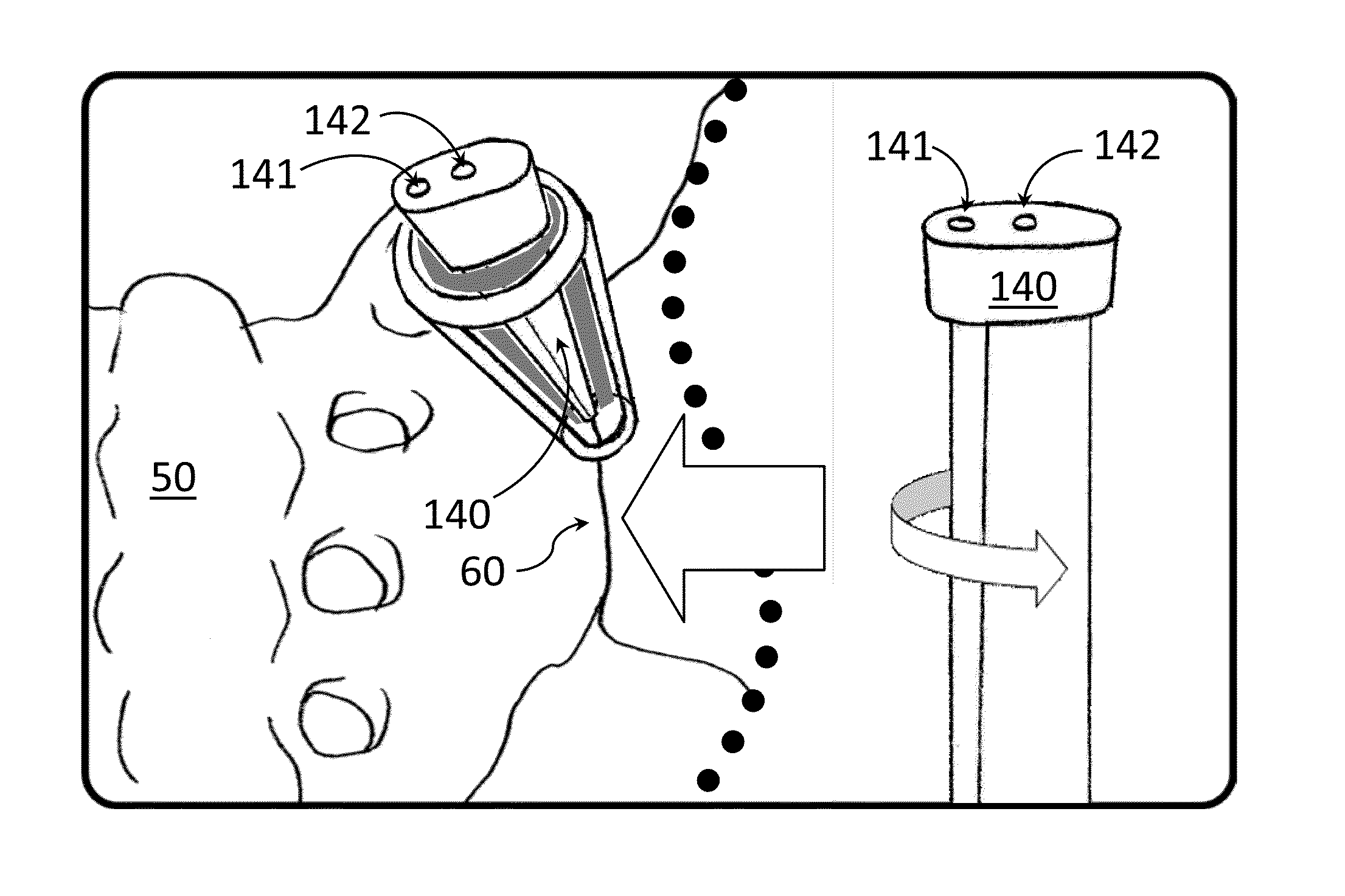
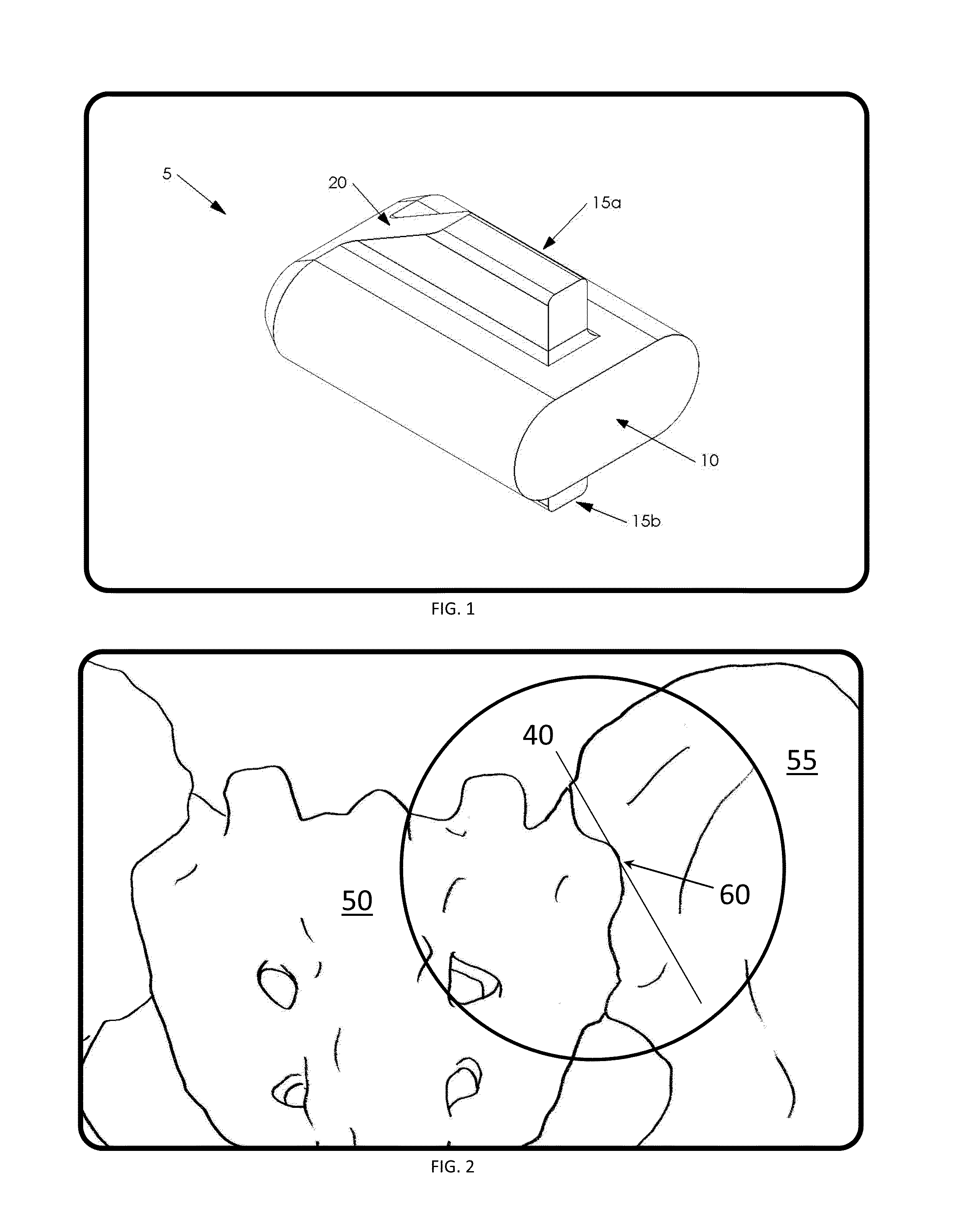
[0047]Referring now to FIG. 1, it will there be seen that the novel sacroiliac stabilization implant, disclosed further in U.S. Pat. No. 8,162,981 to Vestgaarden, entitled “Method and Apparatus for Spinal Facet Fusion,” incorporated herein by reference, is denoted as a whole by the reference numeral 5. Stabilization implant 5 generally includes body 10 and at least one stabilizer 15.

[0048]Body 10 is an elongated element having structural integrity. Preferably the distal end of body 10 (and the distal end of stabilizer 15 as well) is chamfered as shown at 20 to facilitate insertion of fusion implant 5 into the sacroiliac joint. Preferably, as depicted in FIG. 1, body 10 has a rounded rectangular cross-section, or an ovoid cross-section, a laterally-extended cross-section, or some other non-round cross-section, so as to inhibit rotation of body 10 about a longitudinal center axis.

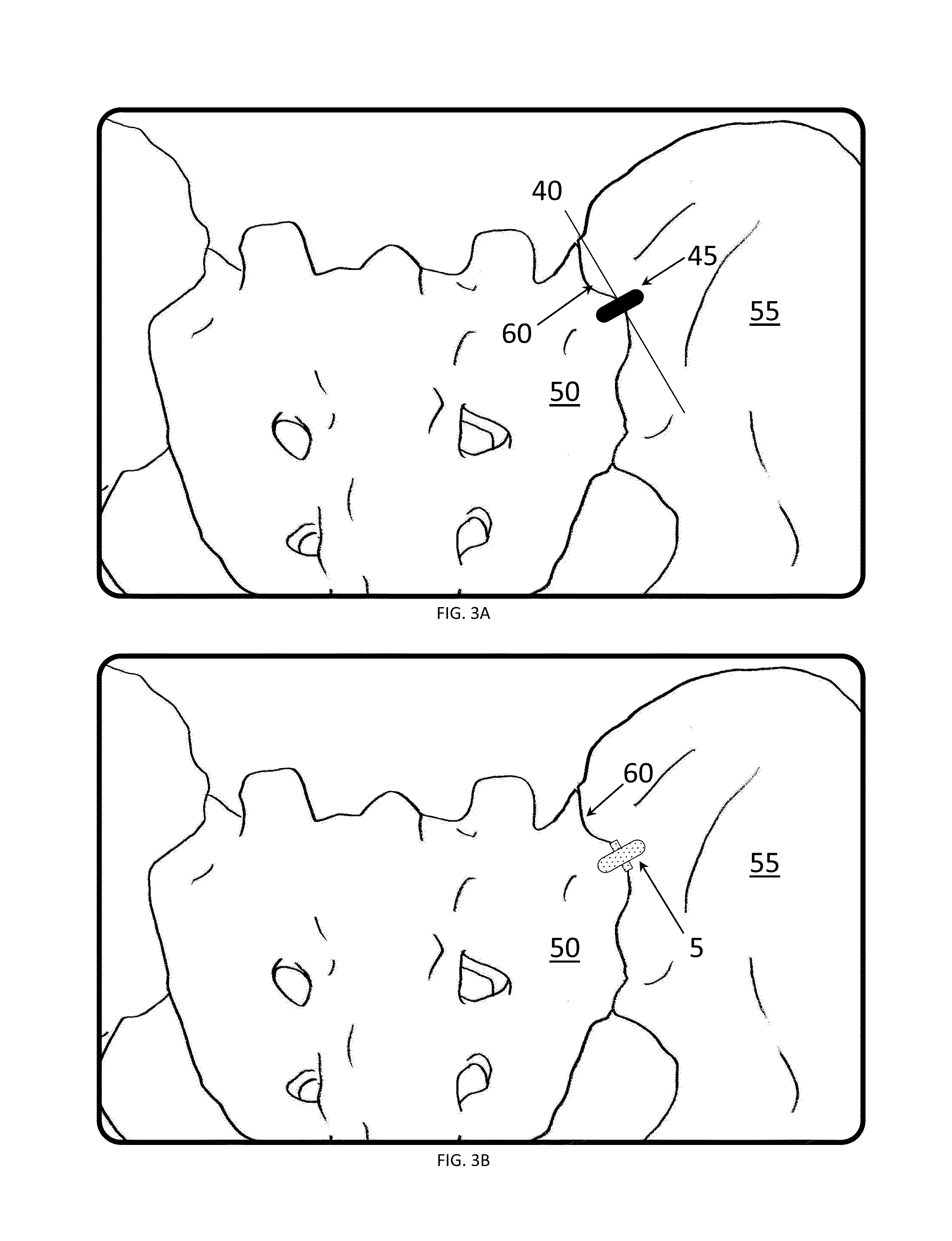
[0049]At least one stabilizer 15 is received in the gap located between the opposing sacroiliac surfaces t...


PUM


Abstract

A method for fusing a spinal sacroiliac joint and a surgical kit. The kit includes a bone-void filler, stabilization device or implant, a guide pin, a joint locator, a set of dilation tubes, a reamer, a novel directional cannula, a novel tapping cap, a novel drill guide, a drill bit, and a novel implant positioner. The method includes the steps of locating the sacroiliac joint, retracting the soft tissue exposing the graft site, removing any bone obstructions and preparing a relatively smooth graft site horizontal to the immediate sacroiliac joint, creating a cavity in the ilium and sacrum to a predetermined depth that spans the sacroiliac joint, inserting a novel stabilization implant into the cavity, and seating the implant within the cavity at a predetermined depth.

Description

BACKGROUND OF THE INVENTION[0001]1. Field of the Invention[0002]This invention relates to surgical methods and apparatus in general, and more particularly to surgical methods and apparatus for fusing sacroiliac joints.[0003]2. Description of the Related Art[0004]Lower back pain is a common ailment among the population and results in pain and suffering as well as loss of work time. Effective treatments for lower back pain will alleviate considerable patient suffering and provide economic benefits by reducing employee absenteeism. Until recently, many complaints of lower back pain and leg pain have been attributed to herniated discs or other injuries to the spinal column. However, extensive therapy and treatment has often been unsuccessful in alleviating such pain. Recently, it has been found that some of this lower back and leg pain can be attributed to symptomatic sacroiliac joint dysfunction or instability.[0005]The sacroiliac joint is located at the juncture of the ilium, the uppe...

Claims


Application Information

Patent Timeline
Patent Type & Authority Patents(United States)
IPC IPC(8): A61B17/56A61B17/17
CPCA61B17/56A61B17/17A61B2017/564A61B17/1739A61B17/025A61B17/68A61B17/1604A61B17/1615A61B17/1662A61B17/7074A61B17/846A61B17/8805A61B2017/0256A61B17/1671
Inventor VESTGAARDEN, TOV, INGE
Owner VG INNOVATIONS
Features
  • Generate Ideas
  • Intellectual Property
  • Life Sciences
  • Materials
  • Tech Scout
  • Unparalleled Data Quality
  • Higher Quality Content
  • 60% Fewer Hallucinations
Learn More