
Computer simulation of electromagnetic fields

Inactive Publication Date: 2014-11-11
VOLD TERJE GRAHAM
View PDF1 Cites 10 Cited by
  • Summary
  • Abstract
  • Description
  • Claims
  • Application Information

AI Technical Summary

Benefits of technology

This patent is about a computer simulation program that can better predict the behavior of electromagnetic fields in a variety of situations. The program uses a triangular mesh and other techniques to accurately model the dipoles and other sources of electromagnetic fields in a virtual space. The program can also incorporate the effects of external and internal boundaries, as well as the discontinuity of the potentials at the boundary. The technical effects of this patent include improved accuracy in predicting the behavior of electromagnetic fields in various situations and the ability to better model the interactions between dipoles and other sources of electromagnetic fields.

Problems solved by technology

Such plots are indistinguishable for retarded and advanced fields and potentials.
In my method, such integrals may be relatively insensitive to the method and crudeness of the approximation to the integral used, compared with prior art.
This generally results in electric current distributions that are more complex; for example, for thin sheets, the result can be written as two distributions of current tangential to the surface, on each side of the sheet and separated by the very small sheet thickness, plus a distribution of current perpendicular to the sheet.
The charge densities for each half-basis charge function vary linearly from the vertex to the perimeter of the associated domain, as in the wires above, but unlike figures for wires above, the colors are not correspondingly graded due to difficulty constructing graphics with graded colors.
The basis set described above has problems for frequencies equal to or near zero, because of the factor of ω in the current: At ω=0, nonzero current cannot be represented by this set of basis functions, and also the set is no longer linearly independent.
This makes a good solution impossible.
While this may give acceptable and even good results, it does not minimize the integrated squared error and it gives measurably inferior results.

Method used


Image

  • Computer simulation of electromagnetic fields
  • Computer simulation of electromagnetic fields
  • Computer simulation of electromagnetic fields

Examples


Embodiment Construction

[0045]Description without Equations

[0046]Introduction

[0047]Much of engineering, including electrical, electronic, and optical engineering, is based on physics and mathematical physics. Physics identifies, or aims to identify, rules or laws of nature using a mathematical language. These general laws of how the world behaves may be used in an infinite number of ways to create or help create specific practical results. Neither the laws of nature nor the language of nature (mathematics) are patentable, while practical inventions that are created by using, combining, and applying them in novel specific ways are patentable.

[0048]But the dividing line between these is not always clear. In development of the methods described in this provisional patent application, I have used some very well established laws of nature (Maxwell's equations of electrodynamics) and some less well known mathematics (geometric algebra) to write or derive some mathematical relationships between physical quantitie...


PUM


Abstract

A system and method for numerically computing electromagnetic fields that is based on extremizing the action integral. The scalar and vector potentials are parameterized. The electromagnetic fields that result from those scalar and vector potentials are derived, and then the parameters are varied to extremize the action integral. In an embodiment, a Lagrangian density is constructed from the electromagnetic fields and potentials. The variation of the action integral is computed as a series of equations in which each equation is the result of taking a derivative of the action integral with respect to a parameter of a Lagrangian density. Solving for the values of the parameters yields the electromagnetic fields.

Description

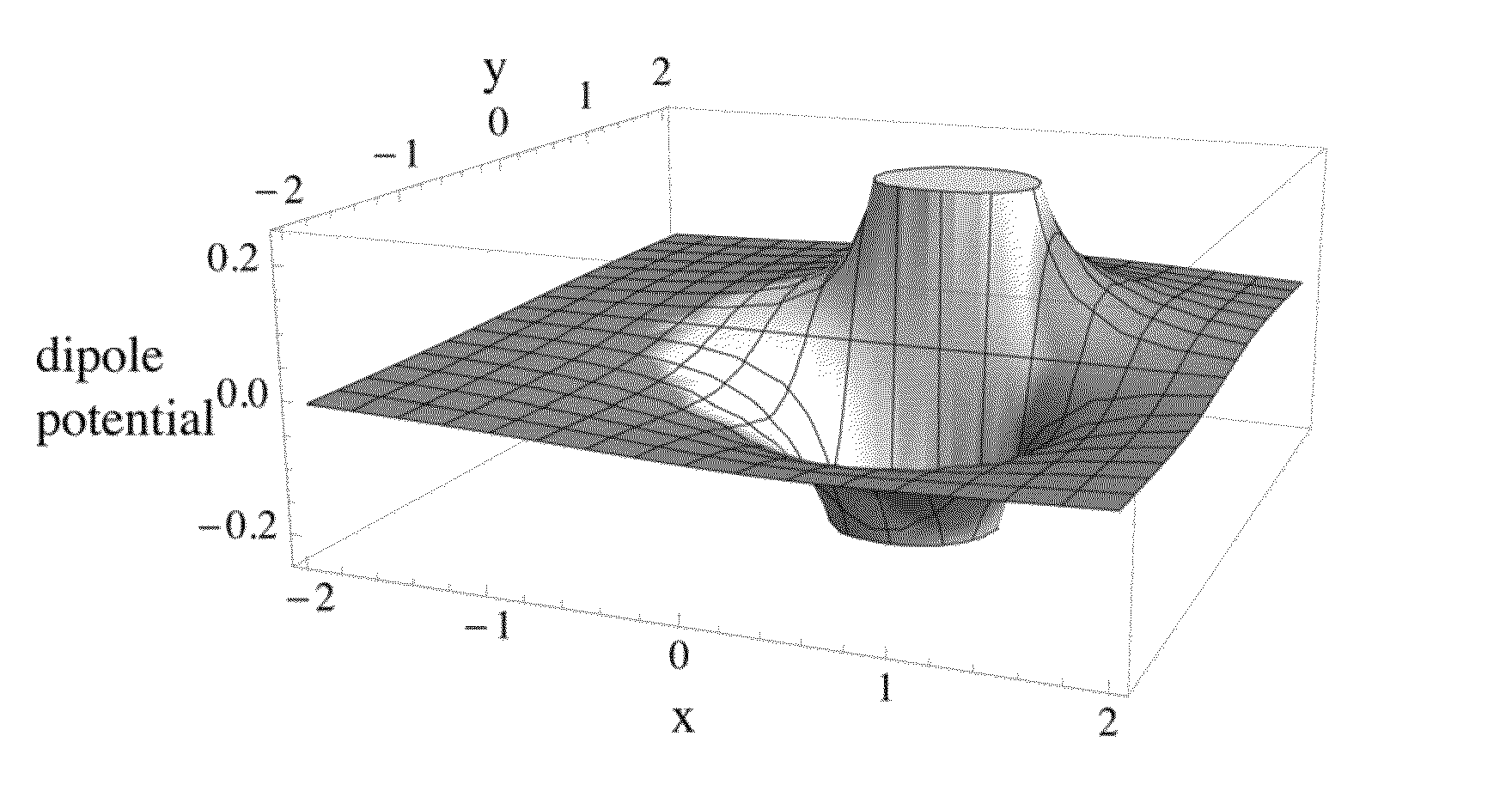
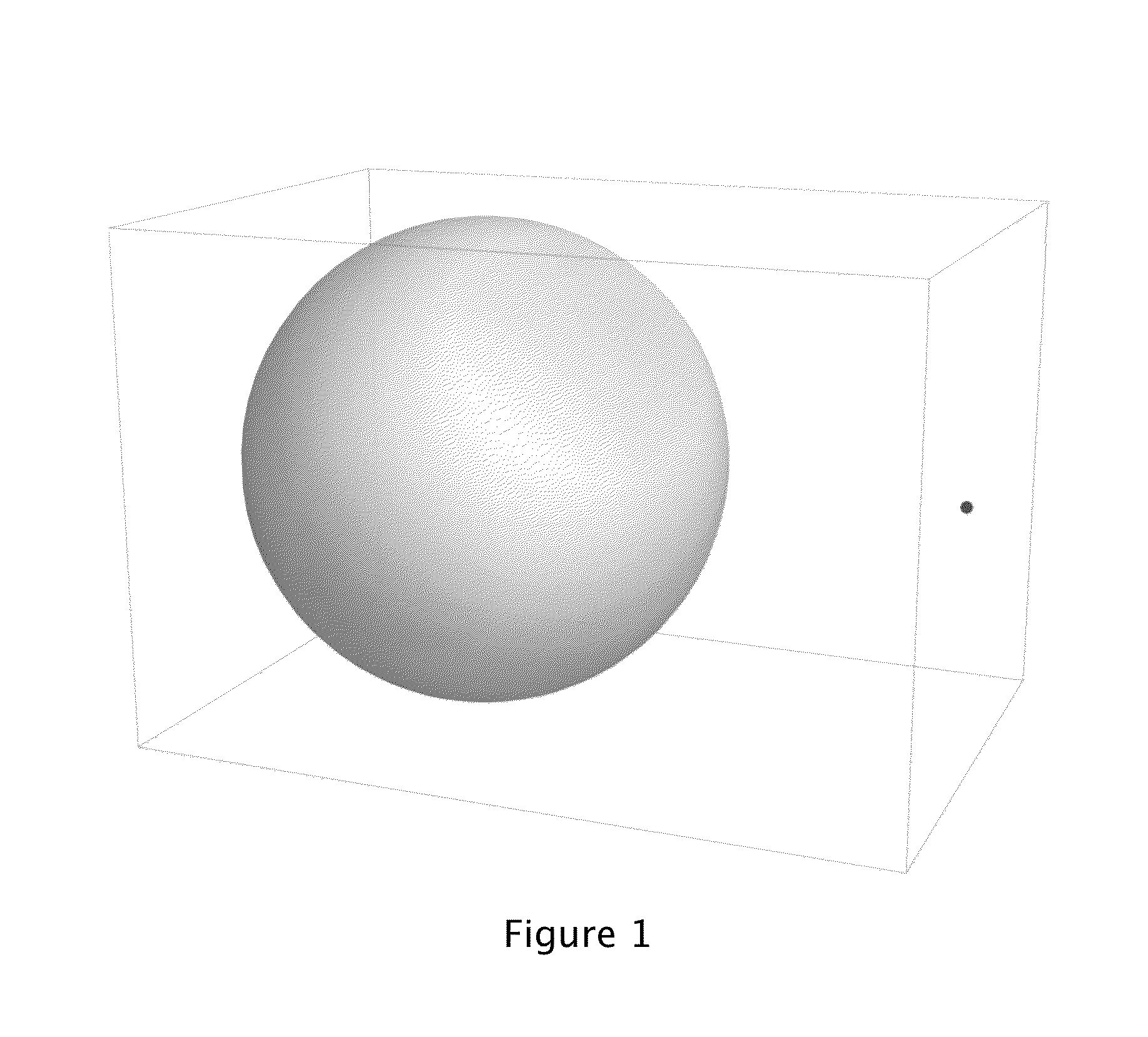
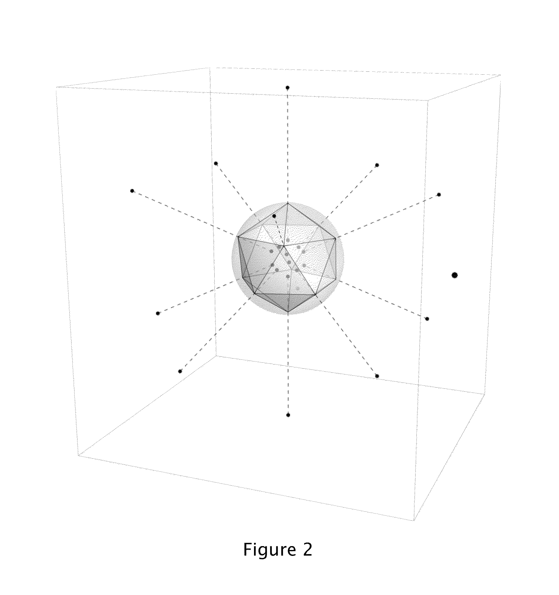
CROSS-REFERENCE TO RELATED APPLICATIONS[0001]This Application claims priority benefit of U.S. Provisional Application Ser. No. 61 / 365,366, entitled Improved Computer Simulations of Electromagnetic Fields, by Terje Vold, filed Jul. 19, 2010, which is incorporated by reference in its entirety.BRIEF DESCRIPTION OF DRAWINGS[0002]FIG. 1 shows a sphere with a nearby physical point dipole, represented as a dot.[0003]FIG. 2 shows these dipole points, colored black; the dashed lines indicate the associations between dipole points and boundary vertices.[0004]FIG. 3 shows the sphere, a dipole in the external region, and a plane containing the dipole and the center of the sphere.[0005]FIG. 4 is a plot of a scalar potential in the plane identified in the previous figure.[0006]FIG. 5 is a plot of a discontinuous scalar potential φi defined in the simulation space made up of the actual mediums inside and outside the sphere.[0007]FIG. 6 shows the sphere, a dipole in the internal region, and a plane...

Claims


Application Information

Patent Timeline
IPC IPC(8): G06F7/60G06F17/10
CPCG06F2217/16G06F7/60G06F17/5036G06F17/50G06F17/5018G06F17/10G06F17/13G06F30/23G06F30/367G06F2111/10
Inventor VOLD, TERJE, GRAHAM
Owner VOLD TERJE GRAHAM
Learn More