Liquid desiccant dehumidification system and heat/mass exchanger therefor

a dehumidification system and liquid desiccant technology, applied in the direction of stationary conduit assemblies, heating types, steam/vapor condensers, etc., can solve the problems of barely meeting demand and peak load of electric utilities

Active Publication Date: 2014-11-18
TECHNION RES & DEV FOUND LTD
View PDF9 Cites 28 Cited by
  • Summary
  • Abstract
  • Description
  • Claims
  • Application Information

AI Technical Summary

Benefits of technology

[0013]According to embodiments of one aspect of the present invention there is provided a heat and mass exchanger for a liquid desiccant air conditioning / dehumidification system having an absorber / dehumidification section with an absorber and a desorber / regeneration section with a desorber, the exchanger comprising: an absorber solution section having an inlet for receiving weak solution from the absorber / dehumidification section and an outlet from which strong solution exits to the absorber / dehumidification section; a desorber solution section having an inlet for receiving regenerated solution from the desorber / regeneration section and an outlet from which solution to be regenerated exits to the desorber / regeneration section; a partition separating the absorber solution section and the desorber solution section; and at least two ports connecting between the absorber solution section and the desorber solution section, including a first port disposed at or proximate the top of said partition and a second port at or proximate the bottom of said partition, thereby facilitating the flow of relatively weak solution from the absorber solution section into the desorber solution section via the first port and facilitating the flow of relatively strong solution from the desorber solution section into the absorber solution section as well as allowing heat transfer between the absorber / dehumidification section and the desorber / regeneration section.

Problems solved by technology

Electric utilities have their peak loads on hot summer days, and are often barely capable of meeting the demand, struggling with brown-out situations.

Method used


Image

  • Liquid desiccant dehumidification system and heat/mass exchanger therefor
  • Liquid desiccant dehumidification system and heat/mass exchanger therefor
  • Liquid desiccant dehumidification system and heat/mass exchanger therefor

Examples


Embodiment Construction

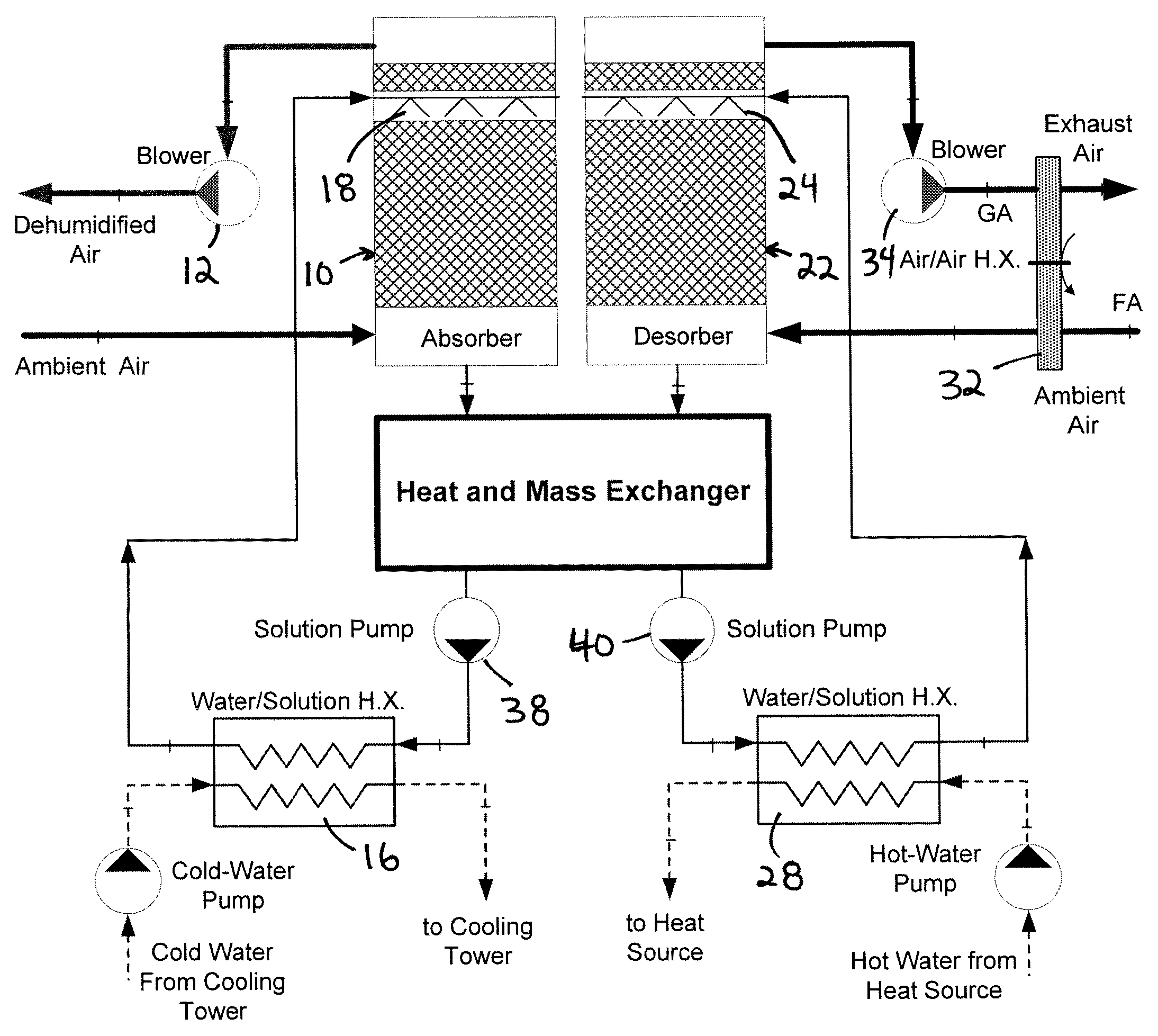
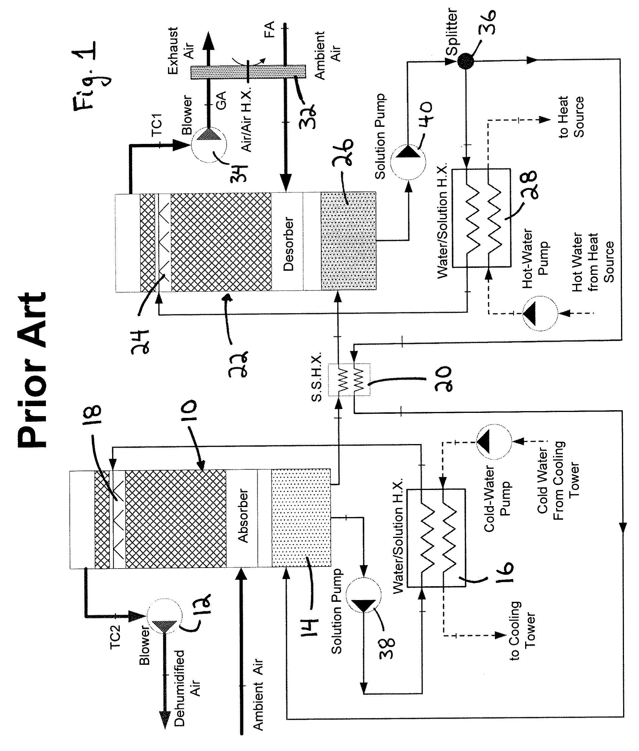
[0021]FIG. 1 shows a prior art liquid desiccant air-conditioning system. Not all details of the workings of the prior art system will be described as the system shown in FIG. 1 is exemplary and many other such liquid desiccant air-conditioning systems can be devised; rather merely a general overview of a prior art system will be provided herein.

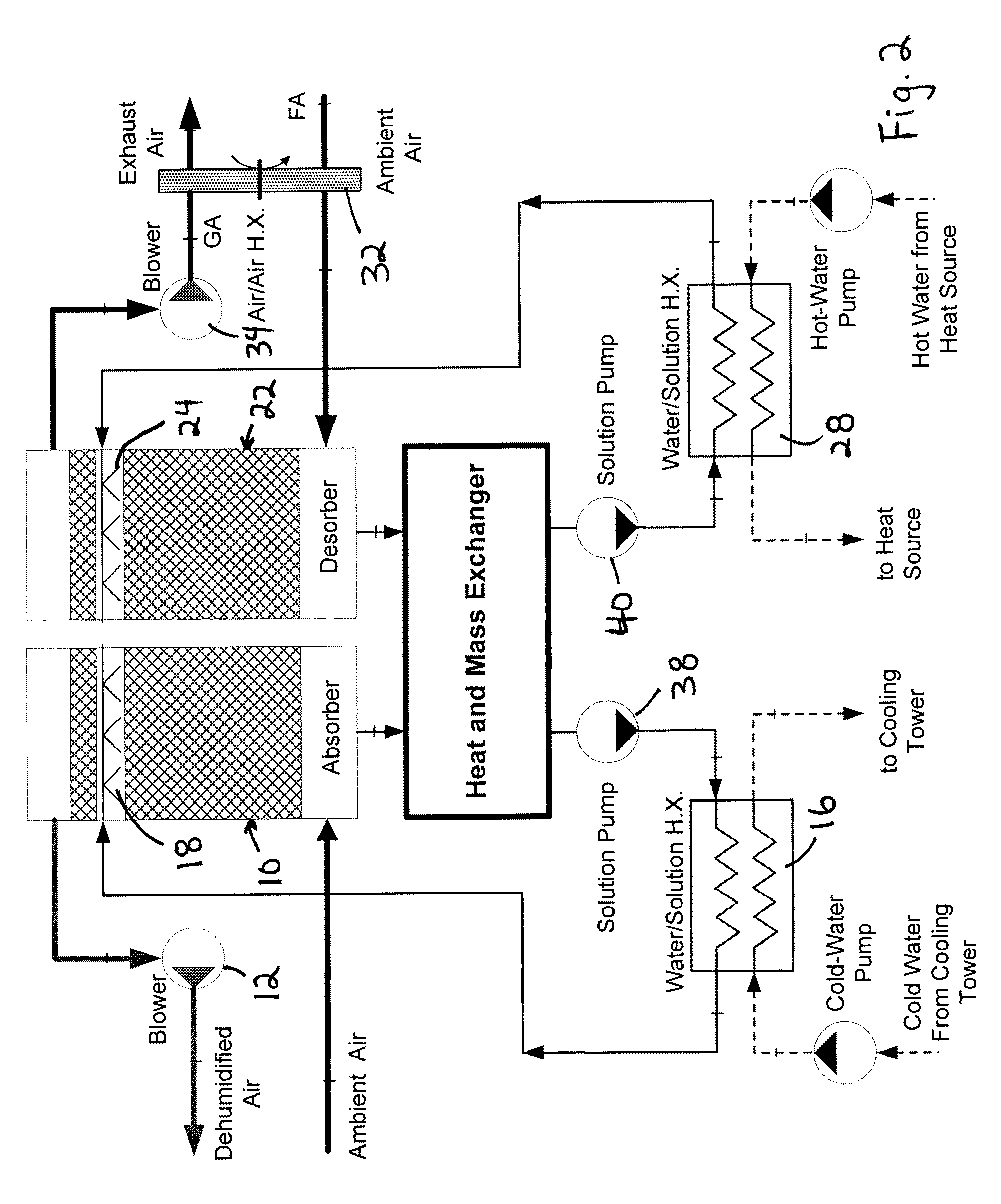
[0022]The prior art system comprises a dehumidifier section (at the left side of the figure) including an absorber (dehumidifier) or absorber tower 10 commonly consisting of an insulated packed tower. Fresh air (e.g. ambient typically warm humid air, air re-circulated from a building, or a combination of both) enters the bottom of the absorber 10; and concentrated absorbent solution (e.g. an aqueous lithium-chloride solution) is delivered to the top of the absorber. The fresh air rises in the absorber 10 and some of the air's moisture is absorbed by descending absorbent solution.

[0023]Water vapor is removed from the humid air stream via absor...


PUM


Abstract

A heat and mass exchanger for a liquid desiccant air conditioning / dehumidification system. The exchanger comprises an absorber solution section operably connected to the system's absorber / dehumidification section and a desorber solution section operably connected to the system's desorber / regeneration section. A partition separating those sections includes at least two interconnecting ports positioned to facilitate flow of relatively weak solution from the absorber solution section into the desorber solution section; and the flow of relatively strong solution from the desorber solution section into the absorber solution section—as well as allowing heat transfer therebetween.

Description

FIELD OF INVENTION[0001]The present invention relates to a dehumidification / air-conditioning system, in particular such a system using a liquid desiccant.BACKGROUND OF THE INVENTION[0002]Growing demand for air conditioning in recent years has caused a significant increase in demand for electrical energy. Global warming, now an undisputed fact, has led to an increase in air conditioning demand not only in hot and humid climates such as in Mediterranean and equatorial countries, but also in European countries with limited air conditioning tradition. Electric utilities have their peak loads on hot summer days, and are often barely capable of meeting the demand, struggling with brown-out situations. With suitable technology, solar cooling systems can help alleviate, if not eliminate the problem. This is a good application for solar energy as the greatest demand for air conditioning occurs during times of peak solar radiation.[0003]A liquid desiccant air-conditioning / dehumidification sys...

Claims


Application Information

Patent Timeline
Patent Type & Authority Patents(United States)
IPC IPC(8): F28B3/00F25B17/00F28C3/04F24F5/00F28D21/00F28D5/00F24F3/14F25B15/00
CPCF24F2003/144F28C3/04F24F5/0014F24F3/1417F28D21/0015
Inventor GOMMED, KHALEDGROSSMAN, GERSHON
Owner TECHNION RES & DEV FOUND LTD
Why Eureka
Try Eureka