Organic light emitting display having improved color shift and visibility

a light-emitting display and organic technology, applied in the field can solve the problems of reducing the amount of light that exits to the outside, reducing the efficiency of light-emitting displays, and low out-coupling efficiency of organic light-emitting displays, so as to reduce the amount of light extraction, reduce color shift, and reduce the effect of color shi

Active Publication Date: 2014-11-25
SAMSUNG CORNING PRECISION MATERIALS CO LTD
View PDF4 Cites 30 Cited by
  • Summary
  • Abstract
  • Description
  • Claims
  • Application Information

AI Technical Summary

Benefits of technology

[0013]Various aspects of the present invention provide an organic light-emitting display which minimizes color shift, increases brightness and improves visibility.
[0033]According to embodiments of the present invention, due to the micro pattern film disposed on the organic light-emitting panel, it is possible to minimize color shift by mixing light from the side with light from the front with little decrease in the amount of light extraction in the central direction.
[0034]In addition, due to the micro pattern film in which the light-absorbing material is dispersed or the circular polarizer film disposed on the micro pattern film, it is possible not only to reduce color shift, but also to increase bright-room contrast ratio (BRCR) and visibility by decreasing reflectivity by blocking external light.

Problems solved by technology

However, the organic light-emitting display has a low out-coupling efficiency, which is problematic.
One of the factors that reduce the light efficiency is that a portion of light travels in an unnecessary direction when exiting from a substrate having a higher refractive index to the air having a lower refractive index and, when incident on the interface between the substrate and the air at an angle greater than a critical angle, totally reflects from the interface, thereby reducing the amount of light that exits to the outside.
The increased brightness results in low power consumption, which leads to increased longevity.
Although the organic light-emitting display having the micro cavity structure exhibits the foregoing advantages, it also has the drawback of a limited color viewing angle that is caused by color shift.
Therefore, since the optical path is increased at the side, the light that resonates and exits is more shifted toward a short wavelength, which is problematic.

Method used


Image

  • Organic light emitting display having improved color shift and visibility
  • Organic light emitting display having improved color shift and visibility
  • Organic light emitting display having improved color shift and visibility

Examples


Embodiment Construction

[0043]Reference will now be made in detail to an optical filter and an organic light-emitting display having the same according to the present invention, various embodiments of which are illustrated in the accompanying drawings and described below.

[0044]Throughout this document, reference should be made to the drawings, in which the same reference numerals and signs are used throughout the different drawings to designate the same or similar components. In the following description of the present invention, detailed descriptions of known functions and components incorporated herein will be omitted when they may make the subject matter of the present invention unclear.

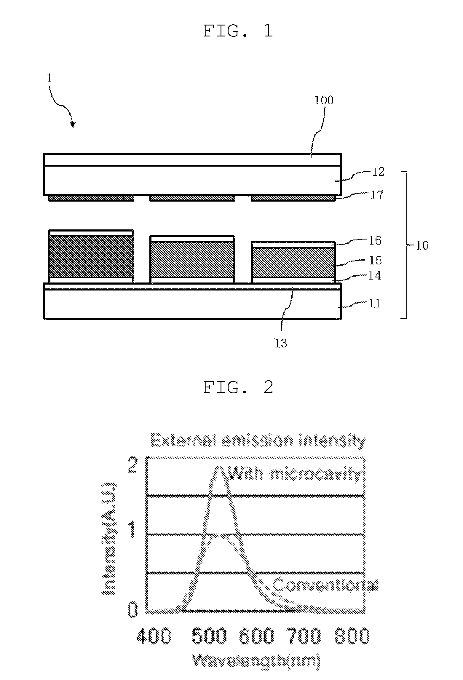
[0045]As shown in FIG. 1, an optical filter 100 according to an embodiment of the present invention is disposed on a front surface of an organic light-emitting panel 10 of an organic light-emitting display 1, i.e. on one surface of the organic light-emitting panel 10 that is in the direction along which light emitted fro...


PUM


Abstract

An optical filter which minimizes color shift, increases brightness and improves visibility and an organic light-emitting display having the same. The optical filter includes a micro pattern film disposed on an organic light-emitting panel. The micro pattern film includes a base material and a micro pattern engraved from the surface of the base material that adjoins the organic light-emitting panel. The micro pattern has a plurality of engraved shapes with a non-circular cross-section which has a depth greater than a width.

Description

BACKGROUND OF THE INVENTION[0001]1. Field of the Invention[0002]The present invention relates to an organic light-emitting display, and more particularly, to an organic light-emitting display which minimizes color shift, increases brightness and improves visibility.[0003]2. Description of Related Art[0004]In general, an organic light-emitting diode (OLED) includes an anode, an organic light-emitting layer and a cathode. When a voltage is applied between the anode and the cathode, holes are injected from the anode into the organic light-emitting layer, and electrons are injected from the cathode into the organic light-emitting layer. Holes and electrons that are injected into the organic light-emitting layer recombine with each other in the organic light-emitting layer, thereby generating excitons. When such excitons transit from the excited state to the ground state, light is emitted.[0005]Organic light-emitting displays including an OLED are divided into a passive matrix type and a...

Claims


Application Information

Patent Timeline
Patent Type & Authority Patents(United States)
IPC IPC(8): F21V9/00G02B5/22
CPCG02B5/201G02B5/223G02B5/22F21V9/00G02F1/1335
Inventor CHO, EUN YOUNGKIM, EUI SOO
Owner SAMSUNG CORNING PRECISION MATERIALS CO LTD
Why Eureka
Try Eureka