Universal clip apparatus for solar panel assembly

a solar panel and universal technology, applied in the direction of solar heat collector mounting/support, photovoltaics, heat collector safety, etc., can solve the problems of difficult installation on site, time-consuming and laborious conventional lug and threaded fastener devices, and inconvenient use, so as to reduce assembly costs, improve quality, and avoid labor costs

Active Publication Date: 2014-11-25
A RAYMOND & CO
View PDF115 Cites 53 Cited by
  • Summary
  • Abstract
  • Description
  • Claims
  • Application Information

AI Technical Summary

Benefits of technology

[0010]The present apparatus and assembly are advantageous over traditional devices. For example, the universal clip apparatus is inexpensive to manufacture and install. Furthermore, the present universal clip apparatus is suitable for pre-assembly to the frame offsite or at a manufacturing plant, thereby improving quality and reducing assembly cost. Moreover, the present universal clip apparatus allows for simple linear frame attachment and increases the electrical grounding continuity and reliability to the solar panel frame as compared to conventional devices. Additional advantages and features of the present invention will become apparent from the following description and appended claims.BRIEF DESCRIPTION OF THE DRAWINGS
[0030]Flexible securing region 62 of universal clip 50 is used to advance universal clip 50 into the channel 38 defined by strut 12 (as shown in FIG. 4). Flexible securing region 62 is compressed to allow universal clip 50 to fit within U-shaped channel 38 and is subsequently released to cause flexible securing region 62 to flex outwardly and bear against sidewalls 30 to thereby removably fix universal clip 50 and panel retainer 52 contained therein into strut 12. Flexible securing region 62 further includes windows 74 that also sit proud with respect to an upper surface of strut 12 when fastening assembly 16 is disposed and secured in strut 12. Housing tabs 80 located along flexible securing region 62 extend away from flexible securing region 62 and contact an inner surface of sidewalls 30 to provide electrical contact with strut 12 and also secure the fastening assembly 16 by engaging downwardly turned edge 36 of strut 12 and thereby preventing unintentional dislodging. The electrical contact may be used to ground solar panel assembly attachment apparatus 10 or respective solar panel assemblies 14. Advantageously, the present teachings provide both metallic frame 22 and a frame-to-strut attachment.
[0031]Housing bottom 76 links housing top 66 to flexible securing region 62. Brace 64 is disposed along at least a region of housing bottom 76 and / or at least a region of flexible securing region 62 to prevent buckling or excessive compression of universal clip 50. This allows universal clip 50 to retain its shape through an initial installation and, if warranted, through removal and subsequent installation.
[0034]As best shown in FIG. 7, spring 98 extends into a passageway defined by panel retaining slot 94. A portion of spring 98 extends beyond a front portion of panel retainer 52. Although not shown, spring 98 may alternately be contained entirely within panel retainer 52 and still be within the scope of the present teachings. Placement of spring 98 causes it to be pushed upwards when metallic frame 22 is advanced through slot 94 and housing slot 68. Compression of spring 98 along with mating of detents 100 with bores 72 provide fixation of panel retainer 52 within housing 60 and secure metallic frame 22 therebetween while compressing barbs 70 into the bottom surface of frame 22 in a locking manner without the need for tool or threaded screws.
[0035]When fully installed, the solar panel hides a majority of the fastening assembly 16. This feature advantageously deters theft of the solar panel assembly 14 by making it less clear to a casual observer that compression together of the flexible securing regions 62 will allow detachment of the universal clip 50 from strut 12. Universal clip 50 and / or panel retainer 52 are preferably stamped from a Magni coated spring steel, but alternately may be stamped from stainless steel.
[0036]Turning to FIGS. 11-14, in various aspects, a bridge 200 is used to connect universal clips 50 (and thus fastening assemblies 16). The connection of a plurality of universal clips 50 facilitates electrical grounding of the solar panel assembly 10. For example, should each universal clip 50 in a solar panel assembly 10 be electrically connected using bridges 200, only a single terminal universal clip 50 or fastening assembly 16 of the many attached to each strut would need to be electrically grounded through the use of a copper wire or an eyelet to a separately wired circuit. This simplifies installation and reduces installation costs.

Problems solved by technology

These devices, however, solely provide frame retention, and are time consuming and complex to install on a job site, such as on top of a windy roof, which thereby incurs significant labor expense and effort.
This patent highlights many of the disadvantages of this lug and threaded fastener approach.
Furthermore, this conventional lug and threaded fastener device is time consuming and difficult to install on site and is not easily suited for pre-assembly.

Method used


Image

  • Universal clip apparatus for solar panel assembly
  • Universal clip apparatus for solar panel assembly
  • Universal clip apparatus for solar panel assembly

Examples


Embodiment Construction

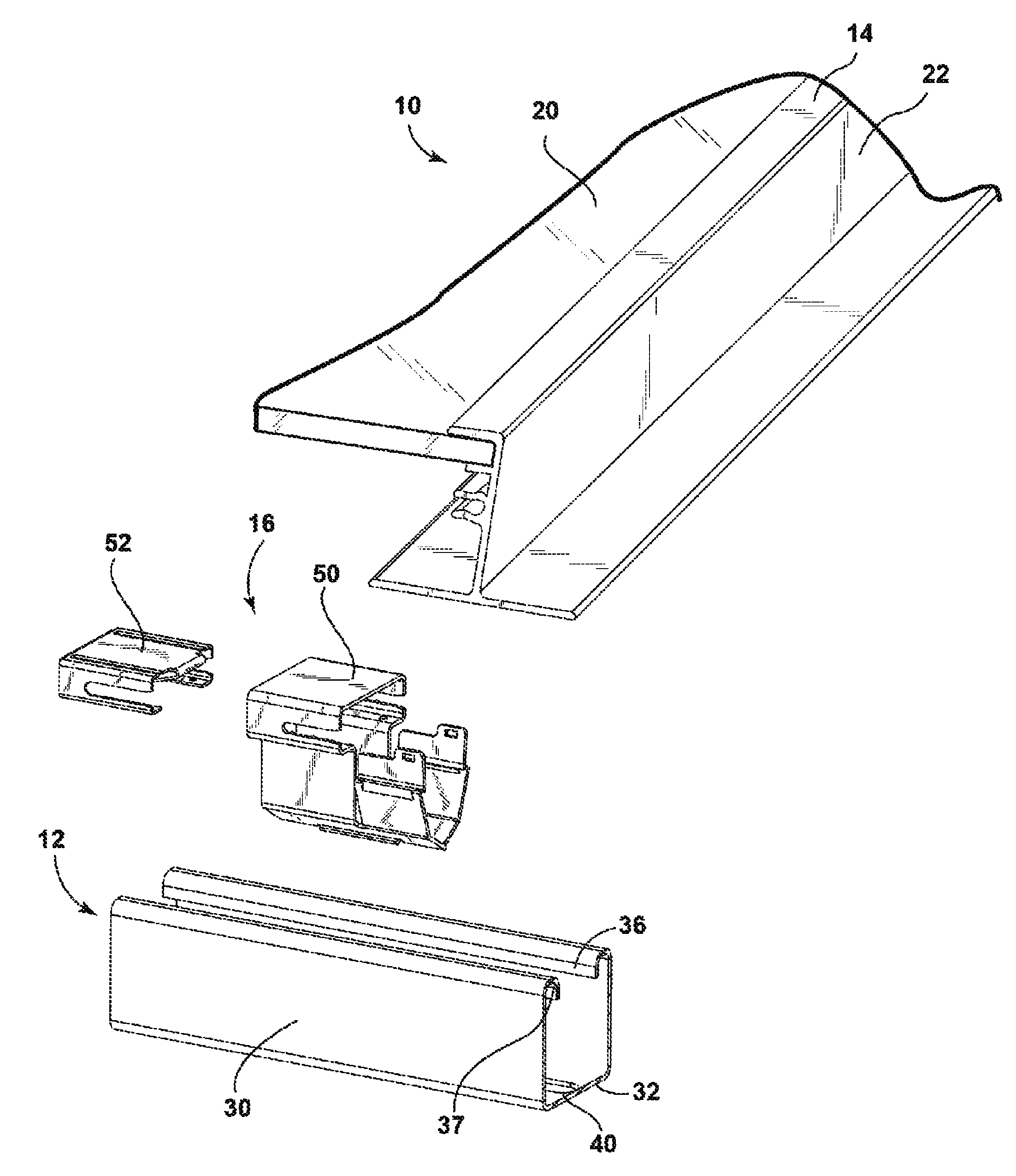
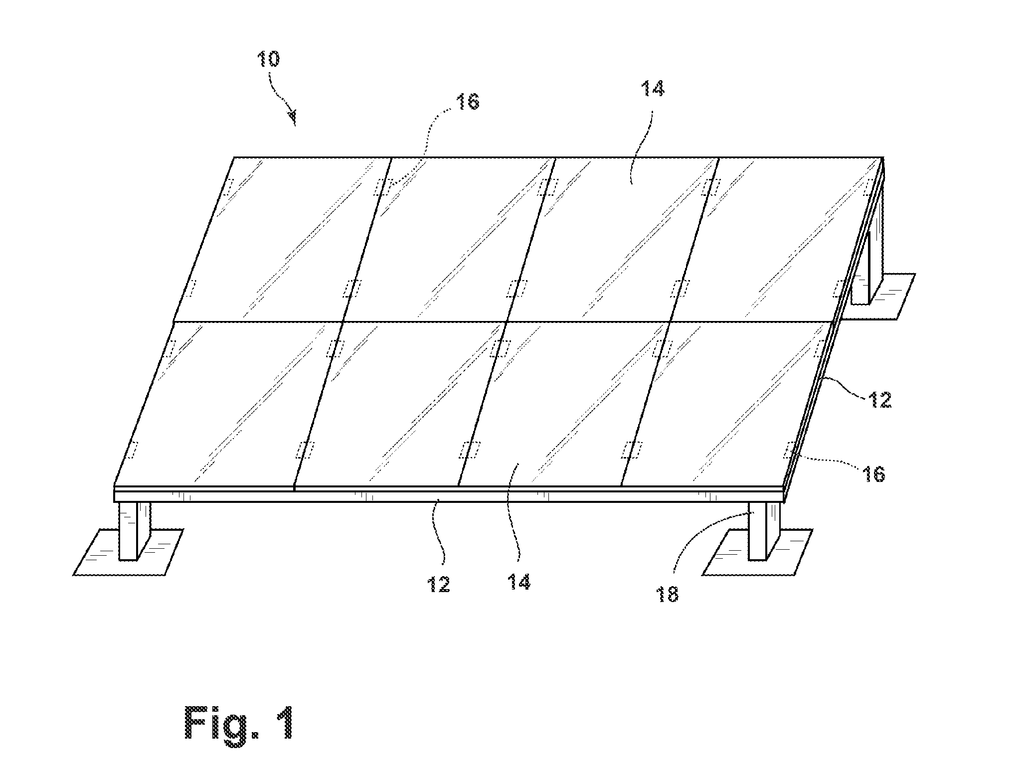
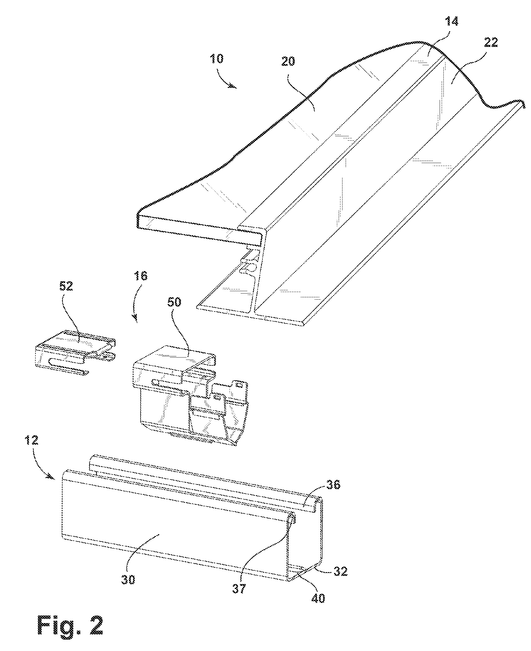
[0026]Referring to FIGS. 1-3, a solar panel assembly attachment apparatus 10 includes elongated and rigid struts 12, solar panel modules or assemblies 14, and fastening assemblies 16. Struts 12 are mounted to vertical legs 18 attached to land, or struts 12 are bolted onto a roof clamp or other structure on a top or side of a building or structure. Each solar panel assembly 14 includes a glass photovoltaic panel 20 and a metallic frame 22, which may be coated with a substrate. Glass photovoltaic panel 20 and metallic frame 22 are provided as a pre-assembled unit or may be provided as separate units.

[0027]As best shown in FIG. 2, strut 12 has a uniform and generally U-shaped cross-section as defined by upstanding sidewalls 30 joined by a bottom wall 32. A reverse-turned wall 34 extends from a top end of each sidewall 30 and terminates in a downwardly directed edge 36. Downwardly directed edge 36 provides a folded-over region of upstanding sidewalls 30 and as detailed below provide att...


PUM

PropertyMeasurementUnit
flexibleaaaaaaaaaa
metallicaaaaaaaaaa
electrically conductiveaaaaaaaaaa

Abstract

A solar panel assembly attachment apparatus is provided including a strut defining a generally U-shaped channel; an electrically conductive grounding clip; and a panel retainer. Upon insertion of the panel retainer into a housing receptacle of the clip, a clip slot and a panel body slot are aligned to allow passage of the portion of the solar panel frame. Advancing the solar panel frame through the aligned clip slot and panel body slot compresses a spring to secure the solar panel frame while barbs electrically connect and provide a ground to the solar panel frame.

Description

CROSS-REFERENCE TO RELATED APPLICATIONS[0001]This application claims the benefit of U.S. Provisional Application Ser. No. 61 / 528,620, filed on Aug. 29, 2011, which is incorporated by reference herein.BACKGROUND AND SUMMARY[0002]The present teachings relate generally to a universal clip apparatus for a solar panel assembly and more particularly to a grounding clip which attaches a solar panel frame to a strut.[0003]Traditionally, peripheral mounting frames holding solar or photovoltaic panels are mounted to a supporting structure on a building roof or on the land through use of threaded fasteners and multi-piece brackets. Exemplary traditional devices are disclosed in U.S. Pat. No. 7,758,011 entitled “Adjustable Mounting Assembly for Standing Seam Panels” which issued to Haddock on Jul. 20, 2010, and U.S. Pat. No. 6,105,317 entitled “Mounting System For Installing an Array of Solar Battery Modules of a Panel-Like Configuration on a Roof” which issued to Tomiuchi et al. on Aug. 22, 20...

Claims


Application Information

Patent Timeline
Patent Type & Authority Patents(United States)
IPC IPC(8): F24J2/46H01R13/648
CPCF24J2/5254F24J2/5232F24J2/5211F24J2002/522F24J2/4607H01L31/0422Y02E10/40F24J2/5256Y02B10/20H02S20/00Y10T29/49117Y10T29/49826Y02E10/50Y02E10/47F24S25/12F24S25/20F24S25/632F24S25/634F24S2025/6007F24S2025/804H02S20/22H02S40/36Y02B10/10F24S40/00
Inventor DUPONT, LUC
Owner A RAYMOND & CO
Why Eureka
Try Eureka