Optical system for head-mounted display

Active Publication Date: 2014-11-25
SEKONIX
View PDF3 Cites 3 Cited by
  • Summary
  • Abstract
  • Description
  • Claims
  • Application Information

AI Technical Summary

Benefits of technology

[0026]According to the present invention, as the angles of principal rays are increased, the angle of view is improved to provide a large screen, and resolution is increased, so that it is possible to appreciate a vivid image due to an increase in the sense of presence and the degree of involvement.
[0027]Further, the optical sy

Problems solved by technology

However, a small display device has a disadvantage in that it is expensive if its resolution is increased.
When an inexpensive and low-resolution display device is used, there is a limit in that the size of the HMD can be no longer reduced.
This imposes restrictions on realizing portability or miniaturization and is problematic in realizing a reduction in weight.
This weight causes fatigue when the user wears the HMD on the head for a long time.
Further, the optical system for the HMD having such a structure g

Method used


Image

  • Optical system for head-mounted display
  • Optical system for head-mounted display
  • Optical system for head-mounted display

Examples


first embodiment

[0054]FIG. 3 shows an optical system for an HMD in accordance with a first embodiment of the present invention.

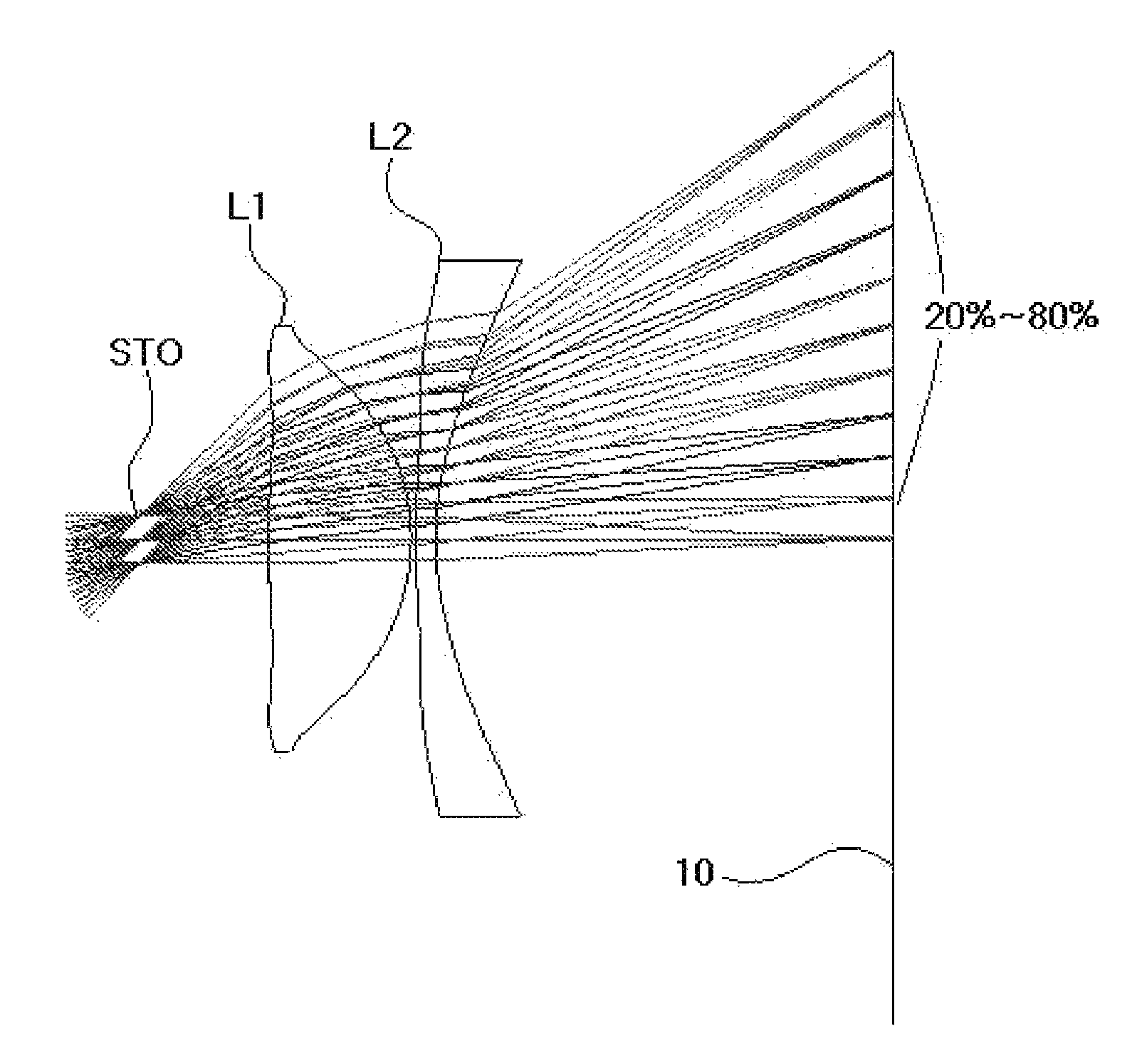
[0055]As shown, a first lens L1 and a second lens L2 are sequentially arranged from the object along an optical axis. Here, the object is a virtual object and refers to a distance from an enlarged image when a user directly recognizes the enlarged image.

[0056]Numerical data of the lenses constituting the optical system according to the first embodiment of the present invention are shown in Table 1 below.

[0057]

TABLE 1Radius ofRefractive AbbecurvatureThickness indexvaluePlane No.(RDY)(THI)(Nd)(Vd)OBJINFINITY2000STOINFINITY11271.48112.311.53155.83−18.6740.43456.5091.701.58530.0525.08739.57IMGINFINITY0(OBJ: Object plane, STO: Stop, IMG: Image plane, and Infinity: Flat plane)

[0058]As shown in FIG. 3, the stop STO is disposed at the side of the object, and the first lens L1 and the second lens L2 are disposed from the stop. When an optical axis direction is set as X, and a direct...

second embodiment

[0072]FIG. 4 shows an optical system for an HMD in accordance with a second embodiment of the present invention.

[0073]As shown, a first lens L1 and a second lens L2 are sequentially arranged from the object along an optical axis. Here, the object is a virtual object and refers to a distance from an enlarged image when a user directly recognizes the enlarged image.

[0074]Numerical data of the lenses constituting the optical system according to the second embodiment of the present invention are shown in Table 4 below.

[0075]

TABLE 4Radius ofThick-Refractive Abbe curvatureness index valuePlane No.(RDY)(THI)(Nd)(Vd)OBJINFINITY2000STOINFINITY10267.05411.181.53155.83−20.6750.20449.5071.801.58530.0522.83441.82IMGINFINITY0(OBJ: Object plane, STO: Stop, IMG: Image plane, and Infinity: Flat plane)

[0076]As shown in FIG. 4, the stop STO is disposed at the side of the object, and the first lens L1 and the second lens L2 are disposed from the stop. When an optical axis direction is set as X, and a d...

third embodiment

[0087]FIG. 5 shows an optical system for an HMD in accordance with a third embodiment of the present invention.

[0088]As shown, a first lens L1 and a second lens L2 are sequentially arranged from the object along an optical axis. Here, the object is a virtual object and refers to a distance from an enlarged image when a user directly recognizes the enlarged image.

[0089]Numerical data of the lenses constituting the optical system according to the third embodiment of the present invention are shown in Table 7 below.

[0090]

TABLE 7Radius ofThick- Refractive AbbecurvaturenessindexvaluePlane No.(RDY)(THI)(Nd)(Vd)OBJINFINITY2000STOINFINITY102117.59514.411.53155.83−20.6443.50442.9211.801.58530526.60635.29IMGINFINITY0(OBJ: Object plane, STO: Stop, IMG: Image plane, and Infinity: Flat plane)

[0091]As shown in FIG. 5, the stop STO is disposed at the side of the object, and the first lens L1 and the second lens L2 are disposed from the stop. When an optical axis direction is set as X, and a direct...


PUM


Abstract

An optical system for a head-mounted display in which image rays provided from a display device are divergent to form and provide an enlarged image is configured so that first and second lenses are sequentially disposed from an object along an optical axis and provide the enlarged image on an image plane, and angles of principal rays are gradually increased from the optical axis toward the edge of the image plane. Thus, as the angles of principal rays are increased, an angle of view is improved to provide a large screen so that it is possible to appreciate a vivid image due to an increase in the sense of presence and the degree of involvement. The entire size of the optical system can be reduced. The head-mounted display can be made compact and lightweight.

Description

CROSS-REFERENCE TO RELATED APPLICATION[0001]This application claims priority to and the benefit of Korean Patent Application No. 10-2013-0069166 filed in the Korean Intellectual Property Office on Jun. 17, 2013, the entire contents of which are incorporated herein by reference.BACKGROUND OF THE INVENTION[0002]1. Field of the Invention[0003]The present invention relates, in general, to a head-mounted display and, more particularly, to an optical system for a head-mounted display, in which lenses are arranged along an optical axis to allow angles of principal rays incident upon an image plane to be gradually increased, thereby increasing an angle of view, reducing a length of the optical system, and increasing the sense of presence and the degree of involvement[0004]2. Description of the Related Art[0005]Generally, a head-mounted display (HMD) refers to a device that is worn on the head of a user, has an optical system embedded therein, and enables the user to enjoy large images in fr...

Claims


Application Information

Patent Timeline
IPC IPC(8): G02B15/14G02B27/14
CPCG02B2027/011G02B2027/0123G02B27/0172G02B27/0955G02B25/001G02B17/00G02B27/02
Inventor CHOI, SOON CHULHWANGBO, JUNG HEE
Owner SEKONIX
Why Eureka
Try Eureka