Method and system for locating a laser vibrometer during non-contact scanning
a laser vibrometer and non-contact technology, applied in the field of non-contact scanning, can solve the problems of increasing the time and cost of performing the inspection
- Summary
- Abstract
- Description
- Claims
- Application Information
AI Technical Summary
Benefits of technology
Problems solved by technology
Method used
Image
Examples
Embodiment Construction
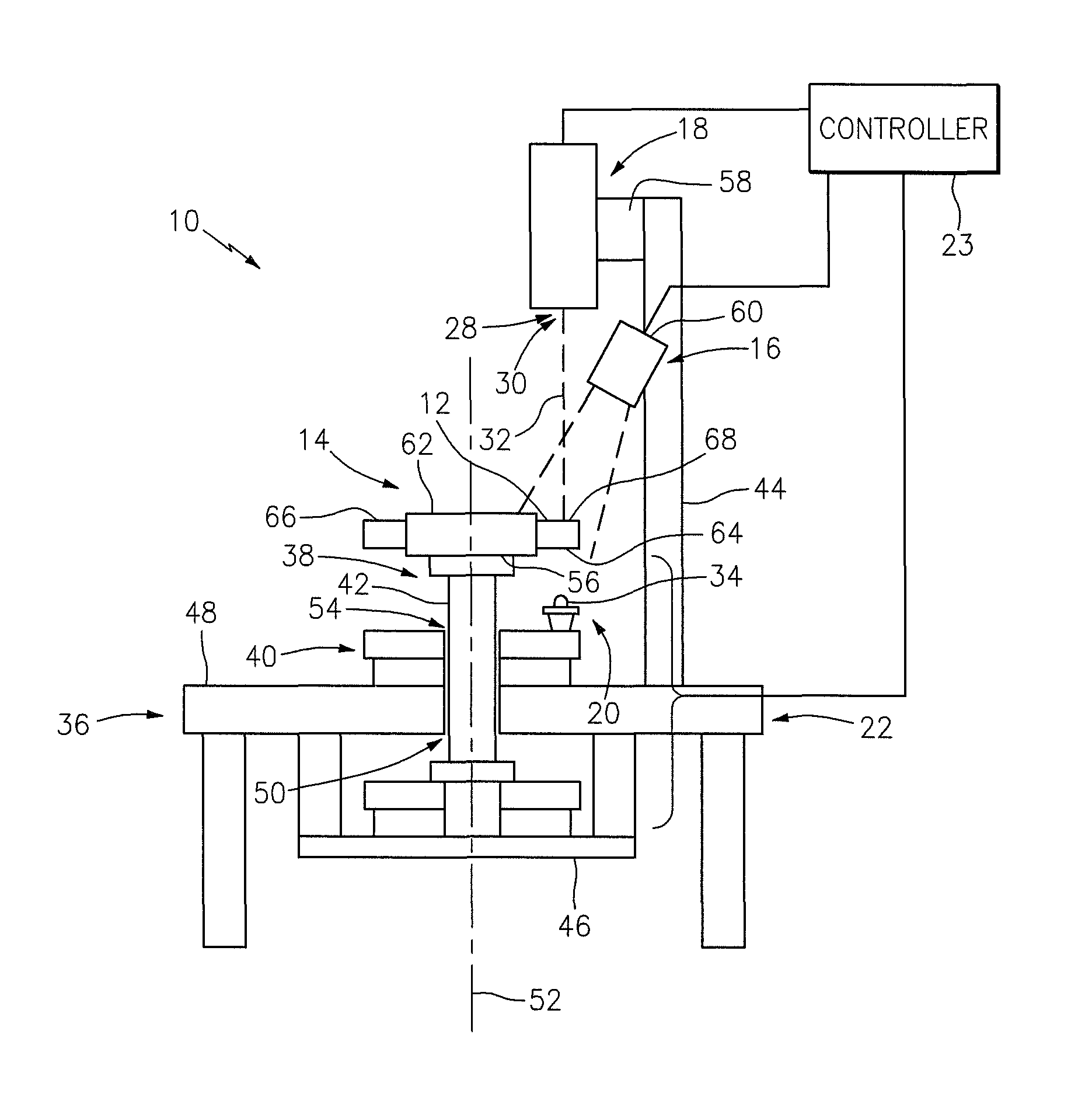
[0012]FIG. 1 illustrates a system 10 for inspecting a surface 12 of an object such as a rotor blade, generally referred to hereinafter as an “object 14”. The system includes an optical scanner 16, a laser vibrometer 18, an excitation system 20, a support stand 22 and a controller 23.
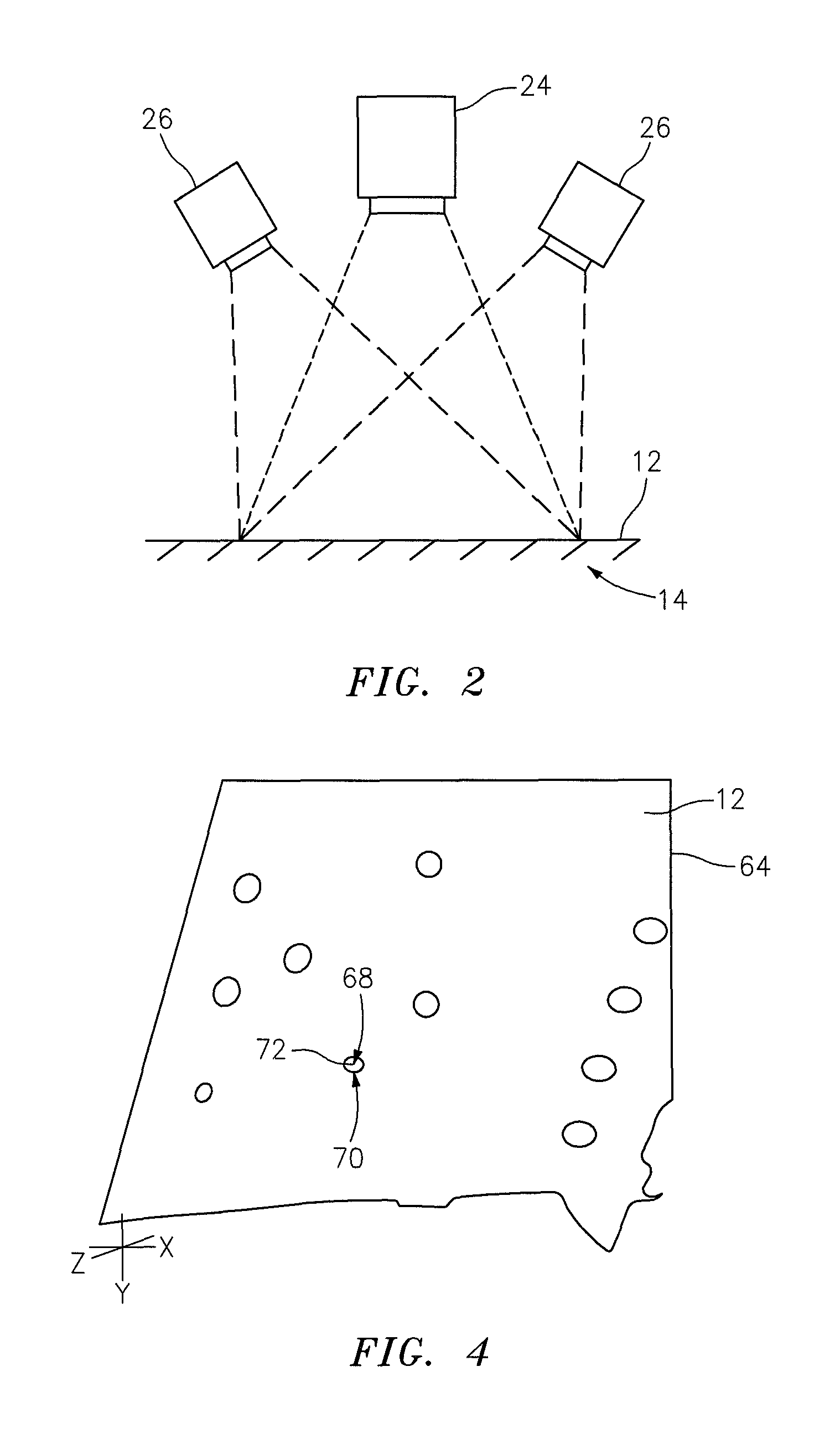
[0013]Referring to FIGS. 1 and 2, the optical scanner 16 is adapted to map at least a portion of the object surface 12. The term “map” is used herein to describe a process of applying a triangulated mesh of surface points to an object surface. In the embodiment shown in FIG. 2, the optical scanner 16 includes a fringe pattern projector 24 and one or more cameras 26. The projector 24 is adapted to project a point, line and / or pattern of light at one or more projection frequencies. Each camera 26 is adapted to capture an image within a light intensity band and a camera frequency band, which camera frequency band includes the projection frequencies. An example of such a projector and cameras is disclosed in...
PUM
 Abstract
Description
Claims
Application Information
 - R&D
- Intellectual Property
- Life Sciences
- Materials
- Tech Scout
- Unparalleled Data Quality
- Higher Quality Content
- 60% Fewer Hallucinations
Browse by: Latest US Patents, China's latest patents, Technical Efficacy Thesaurus, Application Domain, Technology Topic, Popular Technical Reports.
© 2025 PatSnap. All rights reserved.Legal|Privacy policy|Modern Slavery Act Transparency Statement|Sitemap|About US| Contact US: help@patsnap.com


