Eureka AIR delivers breakthrough ideas for toughest innovation challenges, trusted by R&D personnel around the world.

Crystallizer for continuous casting

a technology of continuous casting and crystallizer, which is applied in the field of crystallizer for continuous casting, can solve the problems of reducing the useful limiting the casting speed that can be obtained, and reducing the working life of the crystallizer, so as to reduce the risk of localized cracks forming due to mechanical heat stress, reduce the risk of crack formation, and reduce the effect of cooling capacity

Inactive Publication Date: 2014-12-02
DANIELI & C OFF MEC SPA
View PDF5 Cites 0 Cited by
  • Summary
  • Abstract
  • Description
  • Claims
  • Application Information

AI Technical Summary

Benefits of technology

[0026]In the context of the invention, an essential requisite is that the conical internal shape remains the same as the casting cycles continue, so as to always guarantee the dimensional quality and the shape of the cast product and an optimal contact of the product with the wall of the crystallizer during the solidifying step.
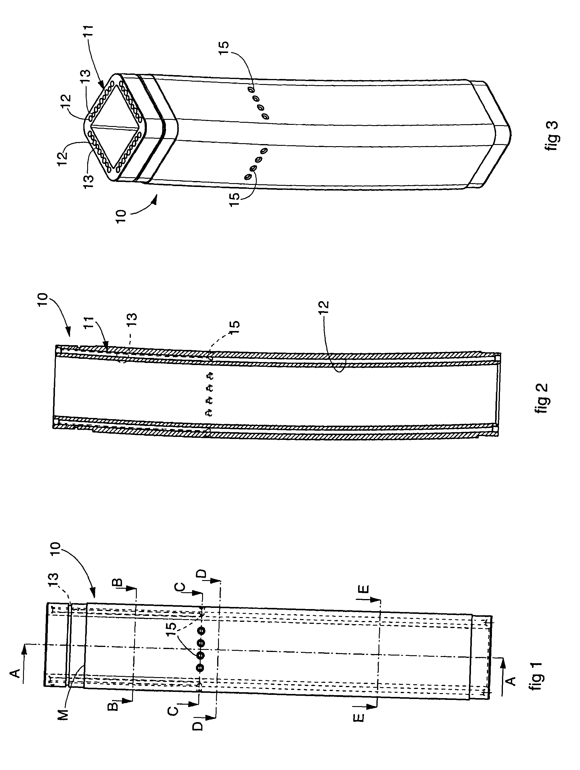
[0027]According to one feature of the present invention, some of the channels in which the cooling liquid flows are geometrically sized so as to define, in a zone substantially astride the meniscus, and in any case comprising the meniscus, an increased transit speed of the cooling liquid: the channels with greater transit speed are alternated in the zone astride the meniscus with channels with lower transit speed. By increased speed we mean that in some of the cooling channels the speed of transit of the cooling liquid is greater in the zone astride the meniscus compared with a zone below the zone astride the meniscus.
[0032]The presence of some of the cooling channels, or segments of the channels, of reduced diameter, the longitudinal extension of which is limited to the zone astride the meniscus, allows to reduce the passage section of the cooling liquid and therefore to increase locally the transit speed of the cooling liquid, consequently intensifying, and in a localized manner, the coefficient of heat exchange and therefore the capacity of removing the heat.
[0033]With the present invention therefore, astride the zone of the meniscus where the temperatures reached and the risk of localized cracks forming due to the mechanical heat stresses are greater, we have an increased cooling capacity thanks to the greater speed of the cooling fluid due to the reduction in section of the channels where the fluid passes.
[0035]In this way we obtain an optimal compromise between the increase in the capacity to remove heat in a localized and specific zone and the losses of load so that, all the parameters of the cooling system (water flow rate, overall dimension of the cooling channels, number of holes and positions etc.) being equal, the strategy of increasing the speed of the cooling fluid only in the localized zone astride the meniscus determines a reduction in the thermal stresses and consequently a lesser plastic deformation of the crystallizer as the casting cycles continue, with a subsequent increase in the working life of the crystallizer in efficient conditions.

Problems solved by technology

As far as the primary cooling system is concerned, in the known type of crystallizers, the high temperatures reached by the internal walls, in particular in the zone around the meniscus, significantly condition the tensional and deformational state of the crystallizer, considerably limiting the casting speeds that can be obtained because of the plastic deformation of the crystallizer and of the consequent drastic reduction in its working life.
Moreover, the variation in the thermal flow in the casting direction, which has a peak in correspondence to the zone of the meniscus, makes the temperature not uniform along the crystallizer, thus causing a non-homogenous deformation state, with subsequent problems connected to the defects in shape which this deformation causes on the cast product and to the premature wear of the crystallizer, which reduces its useful life.
A further problem is connected to maintaining the crystallizer in conditions of efficiency for long periods before having to resort to maintenance and / or replacement, deriving in particular from localized cracks in the zone of the meniscus caused by tensions and plastic deformation accumulated during the heating cycles.
In the crystallizers currently used it has been impossible to find a satisfying solution to all these problems, and indeed the attempt to solve them has instead led to accentuate others.
Thus, for example, in the attempt to increase the casting speed an unsatisfactory cooling of the product being made was obtained, and therefore the solidification of an insufficient thickness of the skin, with subsequent problems of breakage of the skin outside the crystallizer.
On the other hand, when it was tried to obtain an optimal cooling of the product, this entailed a reduction in the casting speed and therefore a reduction in productivity.
However, these documents do not describe any quantitative or qualitative criterion to identify the proportion between the channels with a larger section and channels with a smaller section, and / or their disposition, in the zone astride the meniscus.

Method used


Image

  • Crystallizer for continuous casting
  • Crystallizer for continuous casting
  • Crystallizer for continuous casting

Examples


Embodiment Construction

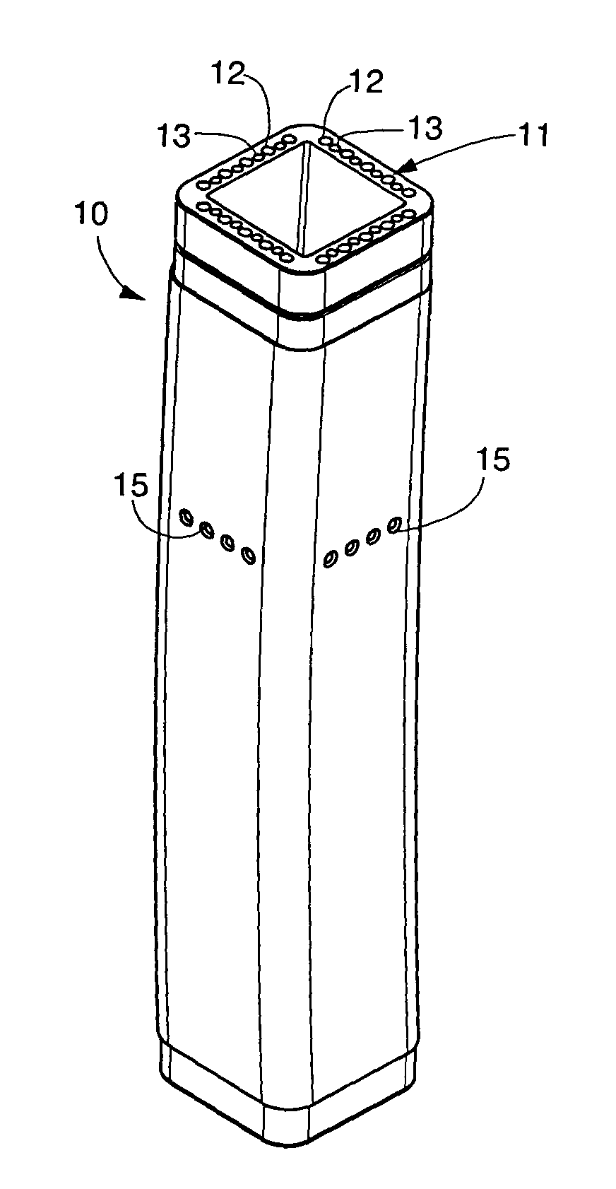
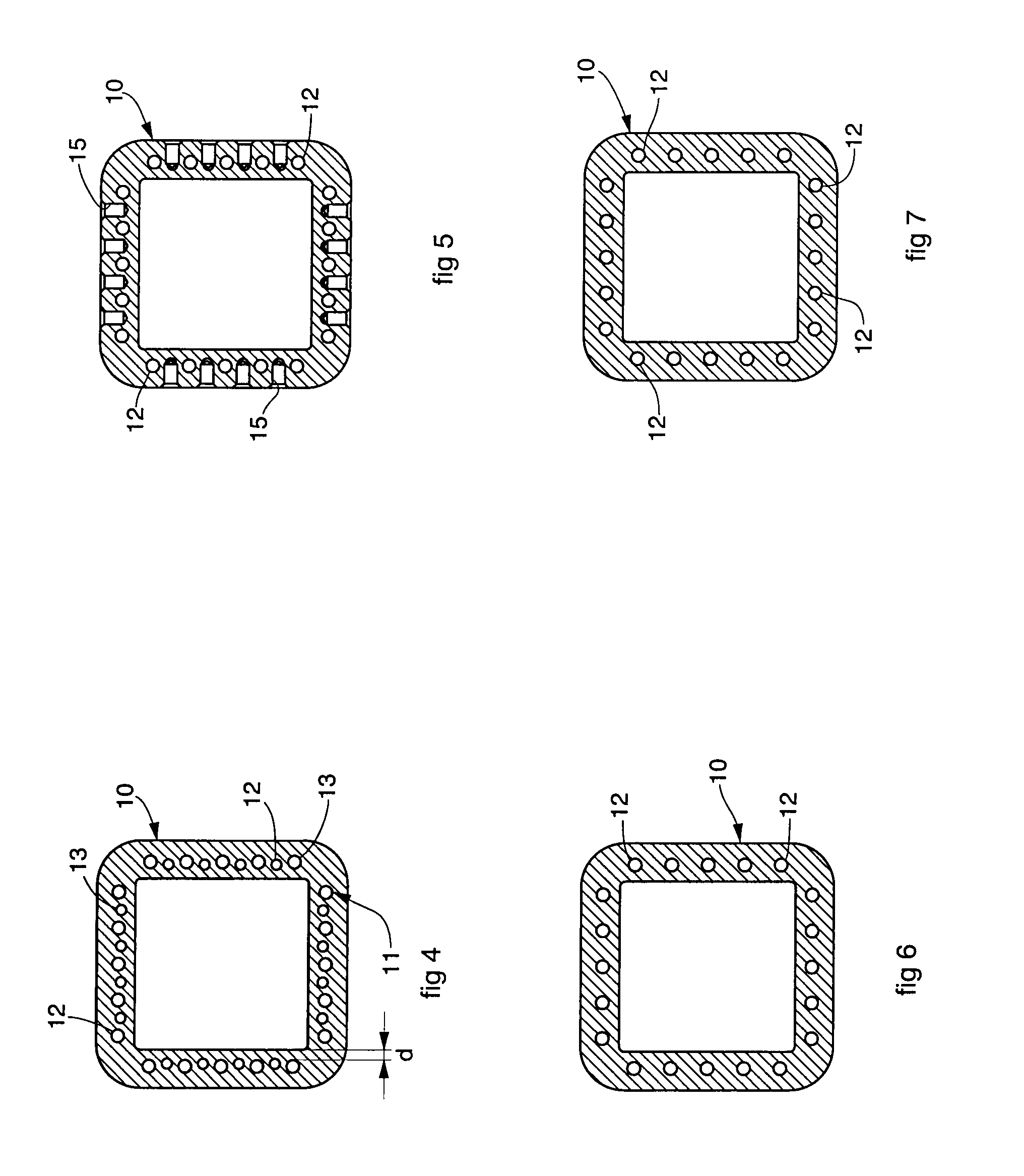
[0050]With reference to the attached drawings, the number 10 indicates in its entirety a crystallizer according to the invention. The crystallizer 10 has a monolithic tubular structure in section, in this case square, with holes / channels, generically indicated with the reference number 11, for the passage of a cooling liquid, made in the thickness of its walls.

[0051]A typical section of the crystallizer 10 is for example square, but this type of section is only an example and in no way limiting in the context of the present invention.

[0052]In the first form of embodiment in FIGS. 1-7, the holes / channels for the cooling liquid 11 are subdivided into two groups, in which the first is formed by holes / channels 12 having a first size (hereafter defined equivalent diameter when their shape is not exactly circular), while the second is formed by holes / channels 13 having equivalent diameter smaller than the first.

[0053]With the term diameter, or equivalent diameter, as it is clear from the ...


PUM

PropertyMeasurementUnit
diameteraaaaaaaaaa
diameteraaaaaaaaaa
diameteraaaaaaaaaa

Abstract

Crystallizer for continuous casting, having a monolithic structure defined by lateral walls in the thickness of which channels (11) are made in which a cooling liquid flows. The channels (11) are geometrically sized so as to define, in a zone substantially astride the meniscus (M), an increased transit speed of the cooling liquid, wherein by increased speed it is intended that in at least some of the cooling channels (11) the speed of transit of the cooling liquid is greater in the zone astride the meniscus (M) compared with a zone below or above said zone astride the meniscus (M).

Description

FIELD OF THE INVENTION[0001]The present invention concerns a crystallizer for continuous casting with a long working life.[0002]The invention is used in the iron and steel field of technology to cast billets or blooms of any type and section, preferably square or rectangular but also polygonal in general, or round.BACKGROUND OF THE INVENTION[0003]In continuous casting, reaching a high casting speed and therefore attaining an always higher productivity, while still maintaining both the surface and internal quality of the cast product high, is connected to the optimization of a plurality of technological parameters relating both to the characteristics of the crystallizer and to the equipment connected to it, and also to the casting method.[0004]Said parameters principally concern the geometric and dimensional characteristics of the crystallizer, the primary cooling system, the lubrication system of the internal walls and the material the crystallizer is made of.[0005]Such parameters a...

Claims


Application Information

Patent Timeline
Patent Type & Authority Patents(United States)
IPC IPC(8): B22D11/055B22D11/041B22D11/124
CPCB22D11/055B22D11/041
Inventor ANSOLDI, MARCOBAZZARO, GIANLUCADE LUCA, ANDREA
Owner DANIELI & C OFF MEC SPA
Why Eureka
Eureka Blog
Learn More