Transmission guide

a transmission chain and guide technology, applied in the direction of belts/chains/gearrings, mechanical equipment, belts/chains/gearrings, etc., can solve the problems of separating the shoe from the base, the guide cannot maintain the proper travel of the transmission chain, and the hook breaks, etc., to suppress wear and damage to the sliding contact surface, and reduce frictional loss

Active Publication Date: 2014-12-02
TSUBAKIMOTO CHAIN CO
View PDF27 Cites 18 Cited by
  • Summary
  • Abstract
  • Description
  • Claims
  • Application Information

AI Technical Summary

Benefits of technology

[0010]Two member molding significantly improves the efficiency with which the guide can be manufactured. In addition, the guide is resistant to shearing forces acting on the shoe both in the longitudinal direction and in the widthwise direction, and the strength of the fused bond between the shoe and the base is significantly increased. Moreover the longitudinal direction retaining mechanism limits movement of the shoe relative to the base and absorbs differences in the thermal expansion and contraction of the shoe and the base, thereby preventing the shoe from separating from the supporting surface of the base.
[0025]In this embodiment, parts of the link plates of the transmission chain closer to the center of the chain can travel without contacting, or while only partly contacting, the sliding-contact surface. Therefore, it is possible to reduce frictional loss that would otherwise occur as a result of friction between the transmission chain and the sliding-contact surface, and to suppress wear and damage to the sliding-contact surface.

Problems solved by technology

The excessive stress can result in breakage of a hook, separation of the shoe from the base, and failure of the guide to maintain proper travel of the transmission chain.
In a chain guide in which the back of a synthetic resin shoe is fused to the base, it is difficult to maintain the bond between the shoe and the base over a long time because, when transmission chain is located eccentrically in the direction of the width of the guide, a widthwise shearing force can cause the shoe to separate for the base.

Method used


Image

  • Transmission guide
  • Transmission guide
  • Transmission guide

Examples


first embodiment

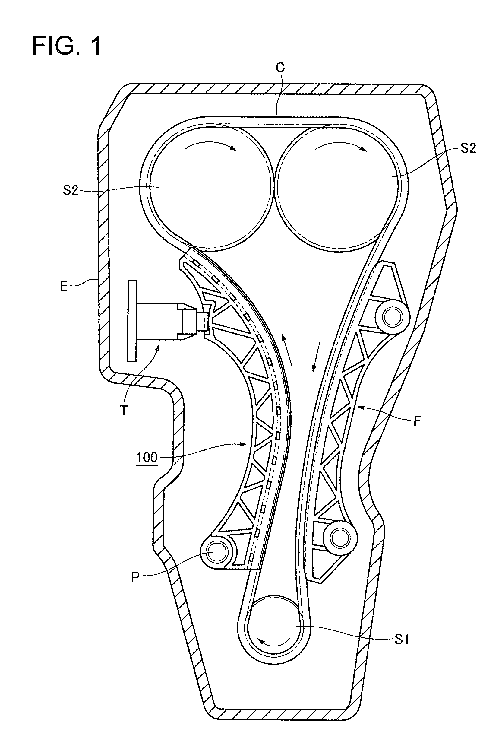
[0046]As shown in FIG. 1, the transmission guide 100 of the first embodiment comprises a crankshaft sprocket S1, camshaft sprockets S2, and a transmission chain C in mesh with the sprockets and arranged to transmit power from the crankshaft of the engine to the camshafts. A movable transmission guide 100 is pivoted on a shoulder bolt P attached to the block of engine E and is in sliding contact with a span of the chain C that travels from the crankshaft sprocket to one of the camshaft sprockets.

[0047]To prevent malfunction of the chain transmission caused by excessive tension or excessive looseness of the chain, a tensioner T applies tension to the chain by acting on the chain through the movable transmission guide 100. A stationary guide F attached to the engine block is in sliding contact with the span of the chain that travels from the other camshaft sprocket S2 to the crankshaft sprocket S1.

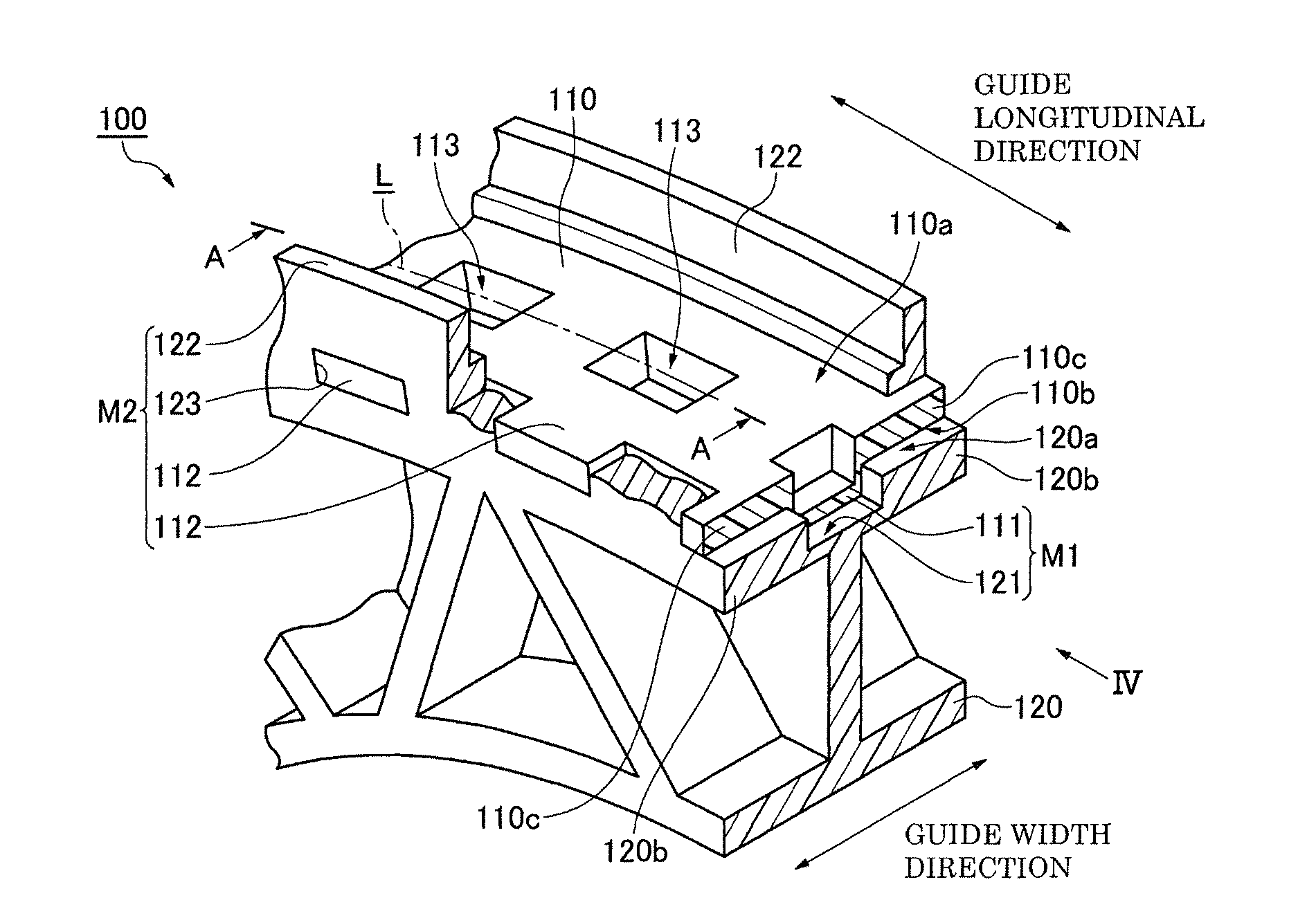
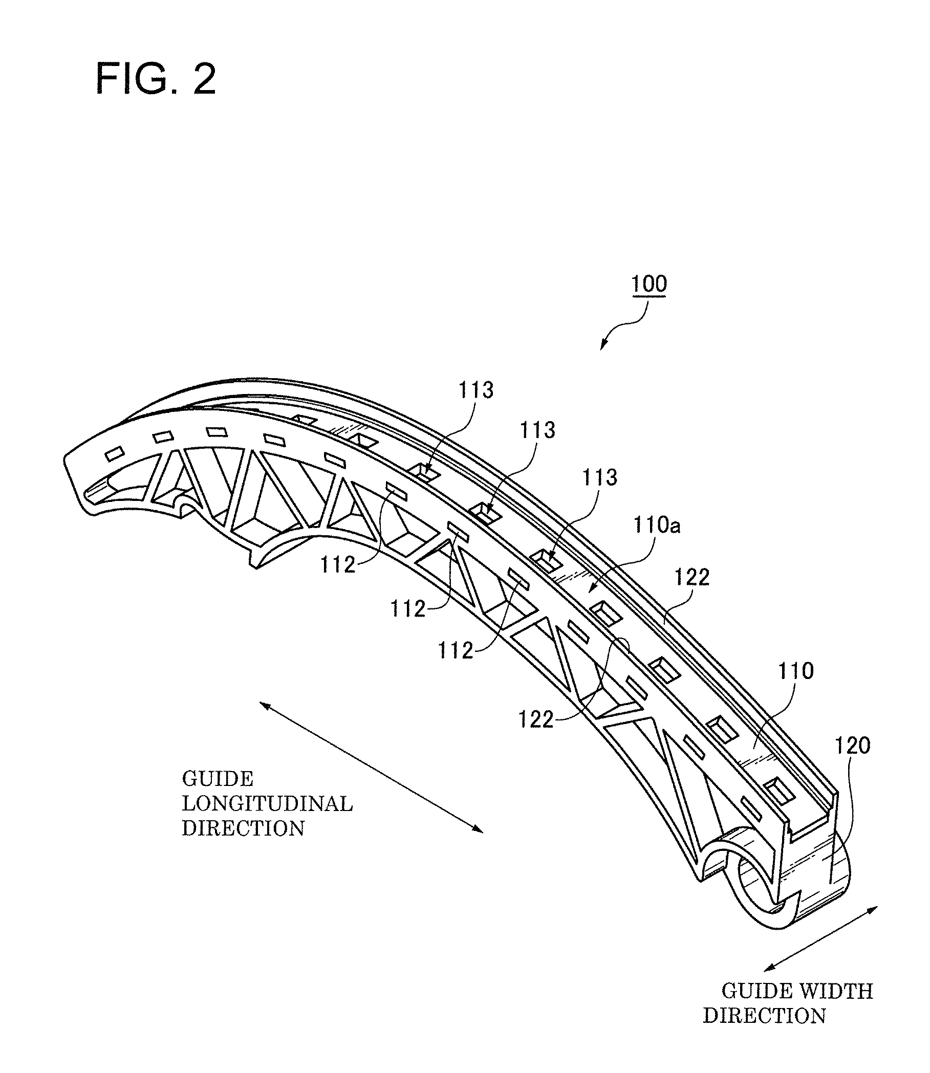
[0048]In the embodiment shown in FIGS. 2-4, the shoe 110 has an elongated sliding contact...

second embodiment

[0063]In FIGS. 7 and 8, which show the guide according to the invention, reference numbers exceed by one hundred the reference numbers of corresponding parts in FIG. 3.

[0064]Protrusions 211 of a synthetic resin shoe 210, and recesses 221 of a synthetic resin base 220, are formed such that their widths gradually decrease, proceeding in the direction of chain travel. i.e., from the chain entry end to the chain exit end of the guide. Each of the protrusions and recesses has a substantially isosceles trapezoidal shape in cross-section, respectively, when seen in a direction perpendicular to the sliding contact surface of the guide as in FIG. 8. The trapezoidal shape of the recesses 221 suppresses shearing forces applied to shoe 210 in the direction of chain travel. The movable guide 200 of the second embodiment of course also exhibits the above-described effects and advantages of the guide 100 of the first embodiment.

[0065]In FIGS. 9 and 10, which show a third embodiment of the guide ac...

fourth embodiment

[0066]In FIGS. 11 and 12, which show the guide according to the invention, reference numbers exceed by three hundred the reference numbers of corresponding parts in FIG. 3.

[0067]Concave recesses 413 in a synthetic resin shoe 410 have a wedge-like shape, tapering in the direction of the width of the guide, proceeding into the shoe from the sliding contact surface 410a in a direction orthogonal to the sliding-contact surface. The narrow edge at the deepest part of each recess extends in the direction of the length of the guide. The wedge-like shape of the recesses 413 enables oil, which accumulates in the recesses, to flow more readily onto the sliding contact surface 410 of the shoe to lubricate a chain traveling thereon. Again, the movable guide 400 of the fourth embodiment also exhibits the effects and advantages of the guide 100 of the first embodiment.


PUM


Abstract

A transmission guide comprises a synthetic resin shoe supported by and integrally molded with a synthetic resin base by two-part molding. A guide length retaining mechanism, which can be formed by one or more protrusions on the back of the shoe and one or more cooperating recesses on the supporting surface of the base, retains the shoe against longitudinal movement relative to the base. A guide width retaining mechanism, which can be formed by projections on the edges of the shoe and cooperating holes formed in side walls extending from the supporting surface of the base, retains the shoe against widthwise movement relative to the base.

Description

CROSS REFERENCE TO RELATED APPLICATION[0001]This application claims priority on the basis of Japanese Patent Application 2011-222884, filed on Oct. 7, 2011. The disclosure of Japanese Patent Application No. 2011-222884 is herein incorporated by reference.FIELD OF THE INVENTION[0002]This invention relates to a transmission guide for use as a stationary guide for guiding a traveling transmission chain, or as a movable guide for applying tension to, and guiding, the chain. A transmission incorporating the guide described herein can be used in an automobile engine, for example, to transmit power by means of an endless roller chain or a silent chain engaged with a driving sprocket and one or more driven sprockets.BACKGROUND OF THE INVENTION[0003]FIGS. 19 and 20 show a conventional transmission guide 800 for use in the timing transmission of an automobile engine. The guide 800 comprises a shoe 810 on which a transmission chain C slides, and a base 820 separately molded and integrally asse...

Claims


Application Information

Patent Timeline
Patent Type & Authority Patents(United States)
IPC IPC(8): F16H7/08F16H7/18
CPCF16H2007/0872F16H7/18
Inventor MORI, KAORIKONNO, MASAHIKOKUREMATSU, YUJI
Owner TSUBAKIMOTO CHAIN CO
Why Eureka
Try Eureka