Radio signal receiving system

a technology for receiving systems and radio signals, applied in the direction of rhombic antennas, pulse techniques, non-resonant long antennas, etc., can solve the problems of poor and inconvenient signal reception, and achieve the effect of improving the efficiency of signal reception and ease of us

Inactive Publication Date: 2014-12-02
YI CHANG HSIANG INDAL
View PDF10 Cites 0 Cited by
  • Summary
  • Abstract
  • Description
  • Claims
  • Application Information

AI Technical Summary

Benefits of technology

[0006]Yet another objective of the present invention is to provide a radio signal receiving system which is easy to use and efficient.
[0009]In an embodiment, the signal processing module comprises: a bandwidth tuning circuit electrically connected to the first switching portion and adapted to spread a spectrum of the radio signal received; a gain amplifying circuit electrically connected to the bandwidth tuning circuit and adapted to keep a signal amplitude of the radio signal within a predetermined range; and a standing wave tuning circuit electrically connected between the gain amplifying circuit and the receiver and adapted to generate the signal according to the radio signal and eliminate impedance mismatch arising from transmission of the signal to the receiver.
[0012]Accordingly, the present invention is characterized in that a radio signal receiving carrier is made from a conventional conducting wire or made of a metal to enhance the efficiency of signal reception and further provide an integrated multifunction radio signal receiving system that features ease of use by a switching means.

Problems solved by technology

However, a conventional external antenna has to work in conjunction with a small antenna or antenna stand on the grounds of cost related limitations and space related limitation, thereby resulting in poor and inconvenient signal reception.

Method used


Image

  • Radio signal receiving system
  • Radio signal receiving system
  • Radio signal receiving system

Examples


second embodiment

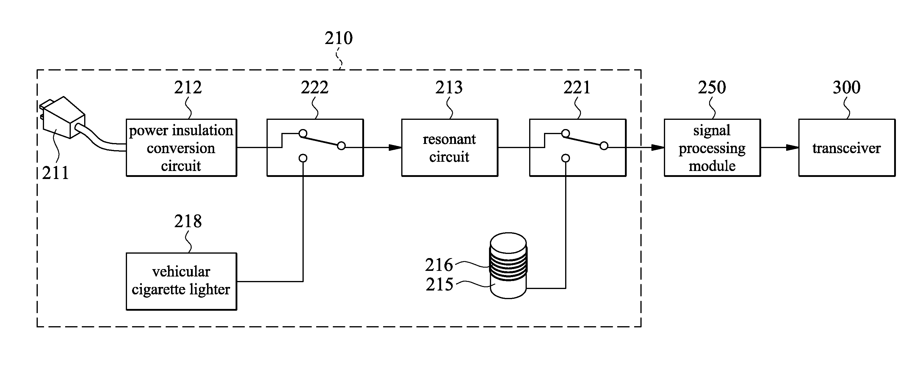
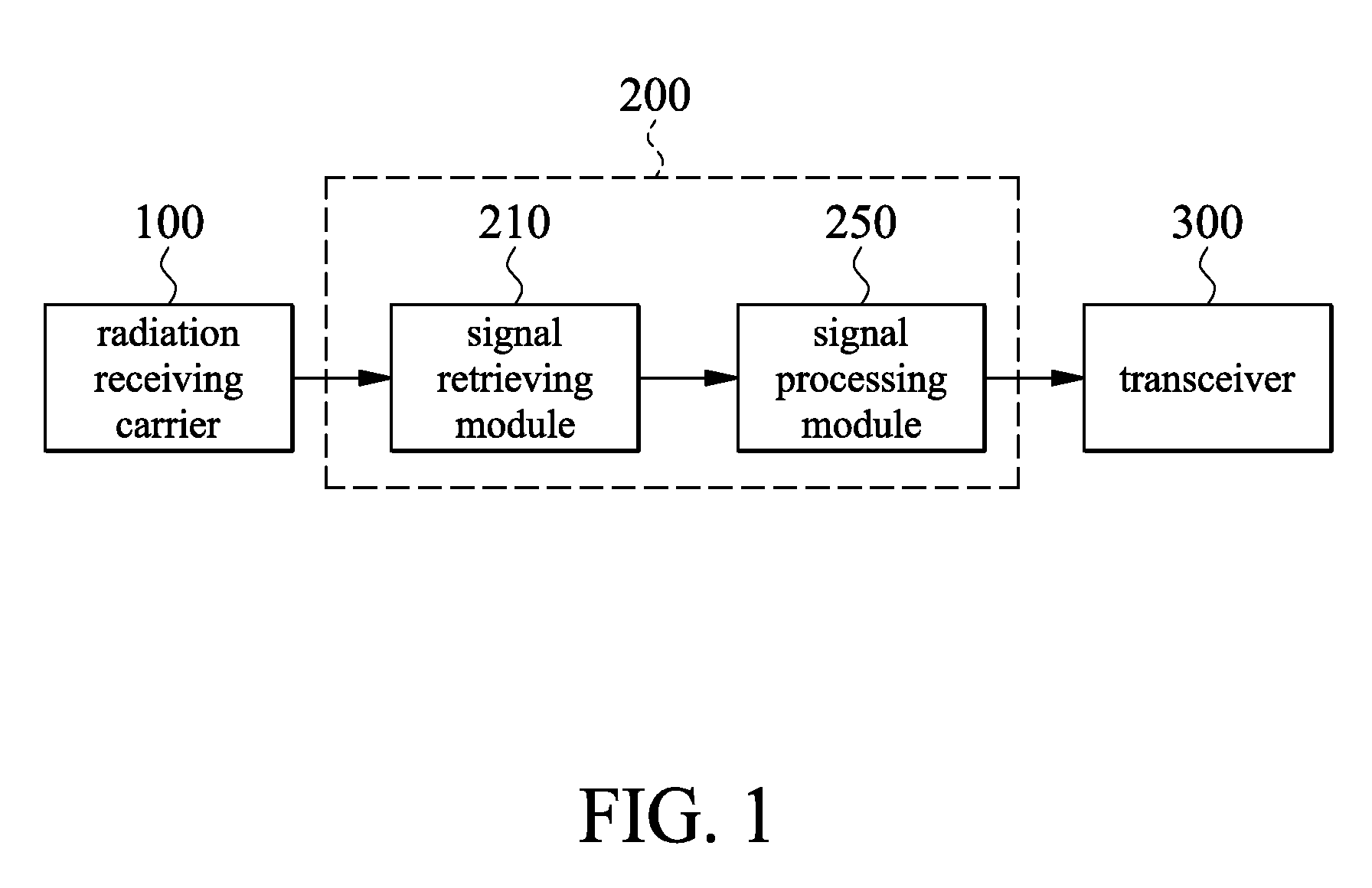
[0028]Referring to FIG. 3B, there is shown a schematic view of the radio signal receiving system according to the present invention. In this embodiment, the signal retrieving module 210 retrieves the radio signal only by means of the metallic vehicular casing which functions as the radiation receiving carrier 100. The signal retrieving module 210 comprises a magnet 215 and a coil 216.

[0029]The magnet 215 is attached to the metallic vehicular casing by magnetic attraction. For instance, the magnet 215 is a cylinder shown in FIG. 3B or a solid of any shape. The coil 216 winds around the magnet 215 and is electrically connected to the signal processing module 250. The coil 216 is capable of current induction. The resonance frequency of the radio signal is identified, by setting the inductance level of the coil 216, such that the radio signal is provided to the signal processing module 250. In this embodiment, the lines of magnetic force of the magnet 215 interact with the metallic vehi...

third embodiment

[0030]Referring to FIG. 3C, there is shown a schematic view of the radio signal receiving system according to the present invention. In this embodiment, a metallic vehicular casing, and a conducting wire in an electrical outlet, both functioning as the radiation receiving carrier 100, are integrated to become one system. In practice, the signal retrieving module 210 and the signal processing module 250 are integrated into a device housing, leaving the power plug 211 (including a connection line connected to the power insulation conversion circuit 212), the magnet 215, and the coil 216 (including a connection line) exposed.

[0031]Given the aforesaid goal of integration, the signal retrieving module 210 comprises a first signal retrieving portion (for retrieving the radio signal by means of the radiation receiving carrier 100, that is, the conducting wire in the electrical outlet), a second signal retrieving portion (for retrieving the radio signal by means of the radiation receiving c...


PUM


Abstract

A radio signal receiving system for providing a signal to a transceiver includes a signal retrieving module and a signal processing module. The signal retrieving module retrieves a radio signal through one of a conducting wire in an electrical outlet, a conducting wire in a vehicular cigarette lighter, and a metallic vehicular casing. The radio signal receiving system operates without any conventional self-contained antenna and includes a radio signal receiving carrier which is either made from a conventional conducting wire or made of a metal to thereby enhance the efficiency of signal reception.

Description

FIELD OF THE INVENTION[0001]The present invention relates to radio signal receiving systems, and more particularly, to a radio signal receiving system capable of operating without any conventional self-contained antenna.BACKGROUND OF THE INVENTION[0002]According to the prior art, a receiver system of an amplitude modulation / frequency modulation (AM / FM) receiver, a digital audio broadcasting (DAB) receiver, and a digital TV (DTV) receiver has to be connected to a self-contained antenna or antenna stand in order to function as a receiving carrier for a radio signal.[0003]However, a conventional external antenna has to work in conjunction with a small antenna or antenna stand on the grounds of cost related limitations and space related limitation, thereby resulting in poor and inconvenient signal reception.SUMMARY OF THE INVENTION[0004]It is an objective of the present invention to provide a radio signal receiving system capable of operating without any conventional antenna or antenna ...

Claims


Application Information

Patent Timeline
Patent Type & Authority Patents(United States)
IPC IPC(8): H04B1/18H04B1/04
CPCH04B1/18H04B1/0458
Inventor WANG, GARY
Owner YI CHANG HSIANG INDAL
Why Eureka
Try Eureka