Memory system and reset method thereof to prevent nonvolatile memory corruption due to premature power loss
a technology of nonvolatile memory and reset method, which is applied in the field of memory system and reset method thereof, can solve problems such as data errors, and achieve the effect of improving data reliability
- Summary
- Abstract
- Description
- Claims
- Application Information
AI Technical Summary
Benefits of technology
Problems solved by technology
Method used
Image
Examples
first embodiment
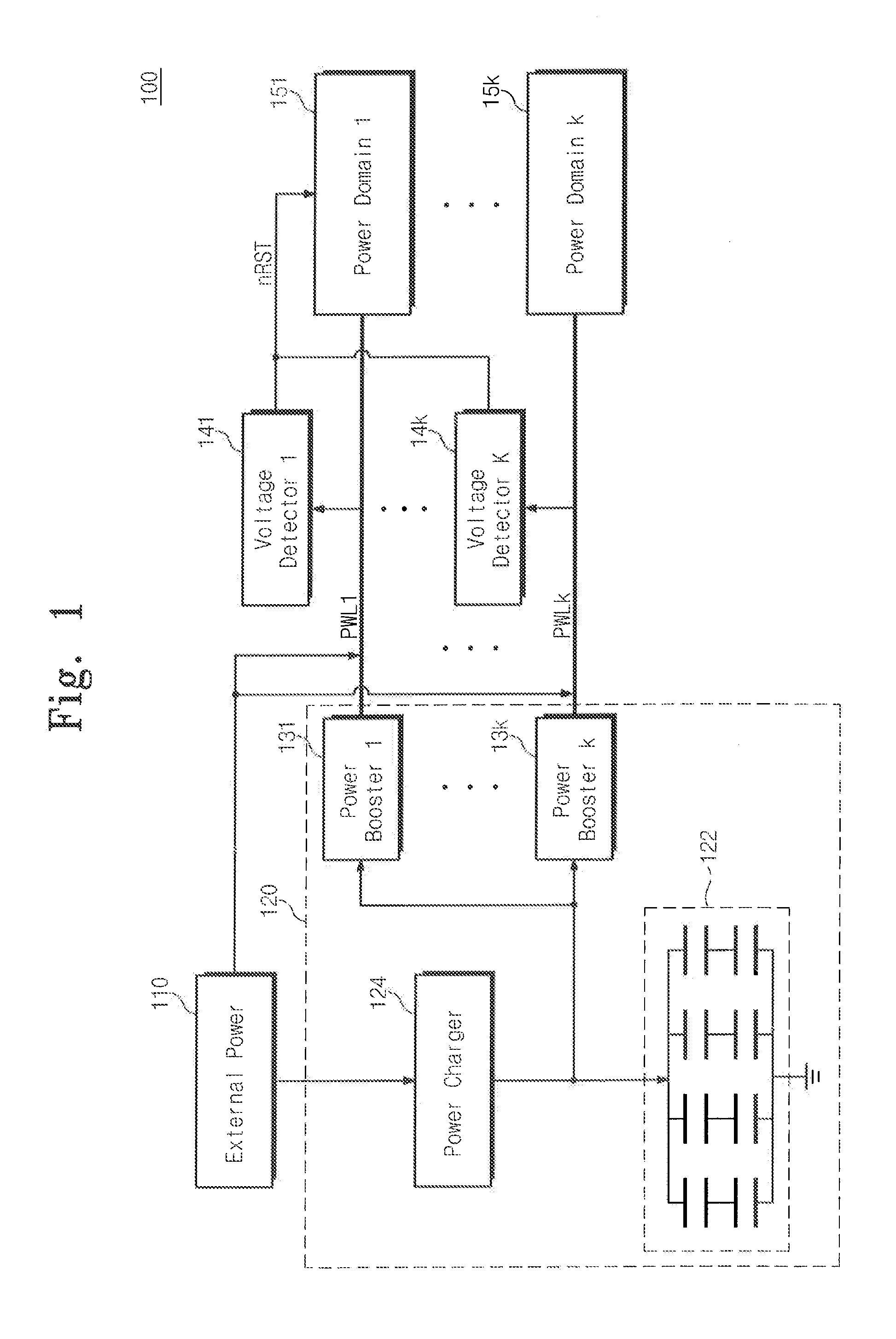
[0046]FIG. 1 is a block diagram illustrating a memory system according to the general inventive concept.
[0047]Referring to FIG. 1, a memory system 100 according to a first embodiment of the general inventive concept includes an external power source 110, an auxiliary power supply 120, a plurality of voltage detectors 141 to 14k, and a plurality of power domains 151 to 15k. Herein, k is an integer equal to or more than two.
[0048]The external power source 110 may receive a Direct Current (DC) power or an Alternating Current (AC) power from the outside to supply a power to a plurality of power lines PWL1 to PWLk or the auxiliary power supply 120. The AC or DC power received may be converted or stepped down to a DC voltage usable by the components of the memory system 100.
[0049]The auxiliary power supply 120 receives power from the external power source 110 to charge at least one charge cell, and auxiliary supplies power, which is outputted from at least one charge cell, to the power li...
second embodiment
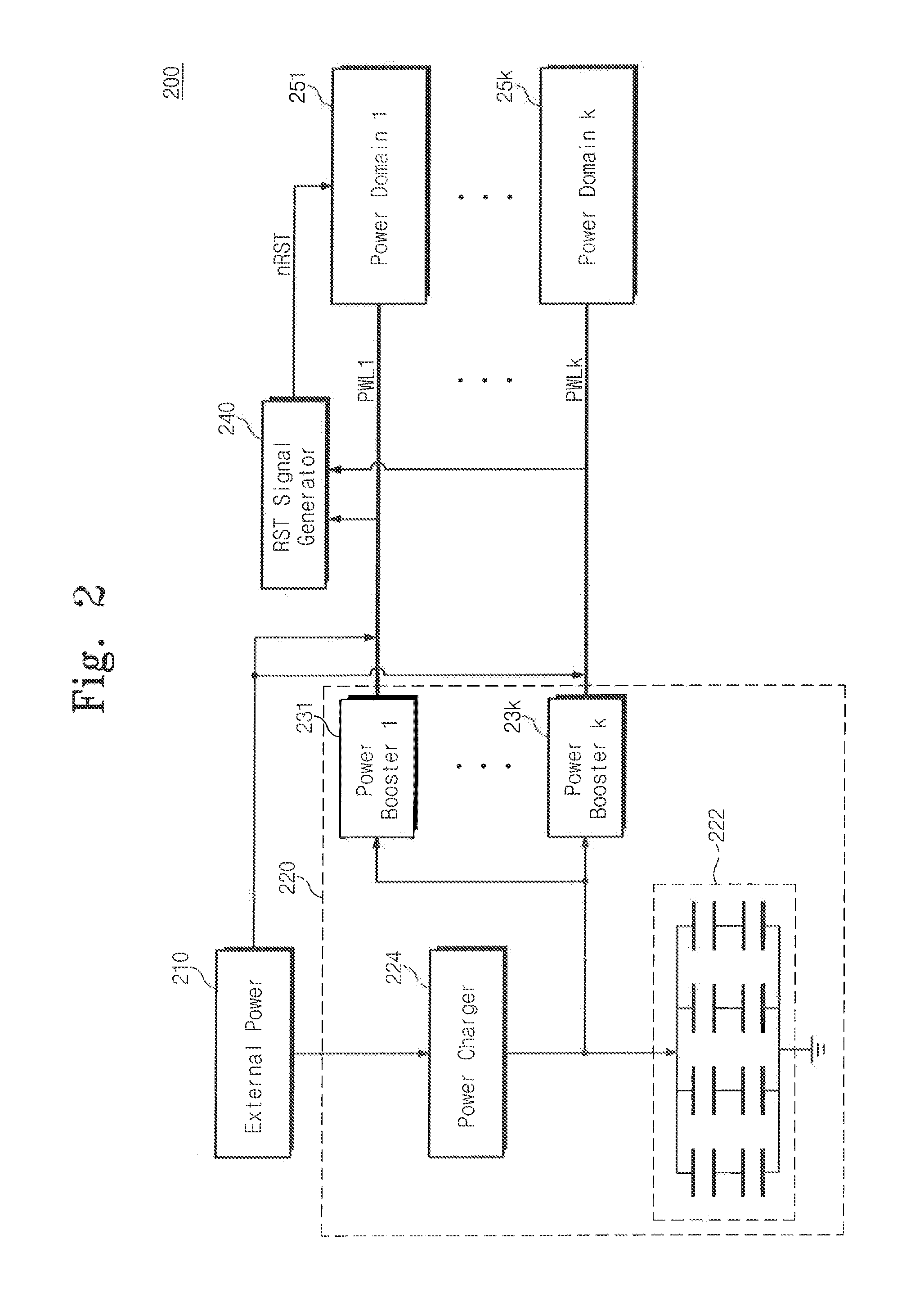
[0066]FIG. 2 is a block diagram illustrating a memory system according to the general inventive concept.
[0067]Referring to FIG. 2, a memory system 200 according to a second embodiment of the general inventive concept includes an external power source 210, an auxiliary power supply 220, a reset signal generator 240, and a plurality of power domains 251 to 25k. Herein, k is an integer equal to or more than two. The configuration and operation of the external power source 210 is the same as those of the external power source 110 of FIG. 1. The configuration and operation of the auxiliary power supply 220 is the same as those of the auxiliary power supply 120 of FIG. 1. The configuration and operation of each of the power domains 251 to 25k is the same as those of each of the power domains 151 to 15k of FIG. 1.
[0068]The reset signal generator 240 detects the voltages of power lines PWL1 to PWLk, and generates a reset signal nRST when at least one of the detected voltages decreases to le...
third embodiment
[0070]FIG. 3 is a block diagram illustrating a memory system according to the general inventive concept.
[0071]Referring to FIG. 3, a memory system 300 according to a third embodiment of the general inventive concept includes an external power source 310, a battery 315, a plurality of voltage detectors 331 to 33k, and a plurality of power domains 341 to 34k. Herein, k is an integer equal to or more than two.
[0072]A plurality of power lines PWL1 to PWLk receive a power from the external power source 310 or receive an auxiliary power from the battery 315.
[0073]Each of the voltage detectors 331 to 33k detects the voltage of a corresponding power line among the power lines PWL1 to PWLk, and thus monitors whether an auxiliary power is normally supplied from the battery 315 when the external power source 310 is shut off. When the auxiliary power is not normally supplied to at least one of the power lines PWL1 to PWLk, a reset signal nRST is generated.
[0074]The memory system 300 according t...
PUM
 Abstract
Description
Claims
Application Information
 - R&D
- Intellectual Property
- Life Sciences
- Materials
- Tech Scout
- Unparalleled Data Quality
- Higher Quality Content
- 60% Fewer Hallucinations
Browse by: Latest US Patents, China's latest patents, Technical Efficacy Thesaurus, Application Domain, Technology Topic, Popular Technical Reports.
© 2025 PatSnap. All rights reserved.Legal|Privacy policy|Modern Slavery Act Transparency Statement|Sitemap|About US| Contact US: help@patsnap.com


