Bone graft delivery device and method of using the same

a bone graft and delivery device technology, applied in the field of orthopedic surgery, can solve the problems of long hospitalization time, long procedure time, complex use of implements, etc., and achieve the effects of preventing or mitigating the risk of injury, facilitating implantation sites, and reducing the risk of infection

Active Publication Date: 2014-12-09
SPINAL SURGICAL STRATEGIES INC A NEVADA CORP D B A KLEINER DEVICE LABS
View PDF634 Cites 39 Cited by
  • Summary
  • Abstract
  • Description
  • Claims
  • Application Information

AI Technical Summary

Benefits of technology

[0019]Also according to a preferred embodiment, the hollow interior portion of the hollow tube further comprises a sloped or curved surface at a second end (e.g. positioned near a place for deposit of bone graft material) adjacent and opposite a lateral window or opening in a lateral face of the hollow tube. As the interior of the hollow tube comprises a sloped or curved surface at its second end, the plunger also comprises a sloped or curved surface at a second end of the plunger. The plunger terminates opposite the curved surface at its second end with a laterally faced surface, which corresponds to the lateral window or opening at the second end of the hollow tube. Thus, in cooperation, the plunger may be inserted into the opening of the hollow tube, and extended the entire length of the hollow tube, at least to a point where the laterally faced surface of plunger is in communication with the lateral window or opening at the second end of the hollow tube. This configuration permits a user to eject substantially all of the bone graft material that is placed into the hollow tube in a lateral direction at the bone graft receiving area during a surgical procedure.
[0039]Embodiments of the present disclosure present several advantages over the prior art including, for example, the speed of the procedure, the minimally invasive aspect of the procedure, the ability to introduce the implant material to the implant site with minimal risk and damage to the surrounding tissue, the lower risk of infection, more optimally placed implant material, a more stable delivery device which is designed to reduce the likelihood of the implant material becoming dislodged prior to fixation, and fewer tools in a surgical site due to the integration of several components required to provide bone graft to a bone graft receiving area. Further, the lower profile of the device allows improved viewing of the area intended for receipt of bone graft material, and use of a reduced set and size of elements therein provided a less expensive device. Also, the device disclosed provides that substantially all of the bone graft material may be ejected from the device and delivered to the surgical site, rather than wasted as unretrievable matter remaining inside the device. The ability to remove substantially all of the bone graft material is of significant benefit because the bone graft material is expensive and / or hard to obtain.

Problems solved by technology

Some disadvantages of traditional methods of spinal surgery include, for example, the pain associated with the procedure, the length of the procedure, the complexity of implements used to carry out the procedure, the prolonged hospitalization required to manage pain, the risk of infection due to the invasive nature of the procedure, and the possible requirement of a second procedure to harvest autograft bone from the iliac crest or other suitable site on the patient for generating the required quantity of cancellous and / or cortical bone.
The traditional devices for inserting bone graft impair the surgeon's visualization of the operative site, which can lead to imprecise insertion of bone graft and possible harm to the patient.
The caulking gun and the collection of large barrel / plunger designs typically present components at the top of their structure which block the view of the surgical site.
Such rough maneuvering can result in imprecise placement of bone graft, and in some cases, rupture of the surgical area by penetrating the annulus and entering the abdominal cavity.
Also, in some surgical procedures, the devices for inserting bone graft material are applied within a cannula inserted or placed in the surgical area, further limiting the size and / or profile of the bone graft insertion device.
When a cannula is involved, some traditional devices such as the large barrel / plunger designs and / or the chalking gun designs simply cannot be used as they cannot be inserted within the cannula.
Such a delivery method causes the bone grafting material to become impacted at the bottom of the delivery device, and promotes risk of rupture of the surgical area by penetrating the annulus and entering the abdominal cavity.
Further, traditional devices that deliver bone graft material along their longitudinal axis may cause rupture of the surgical area or harm to the patient because of the ensuing pressure imparted by the ejected bone graft material from the longitudinal axis of the device.
Many companies provide various forms of bone graft in varying degrees of liquidity and viscosity, which may cause problems in certain prior art delivery devices in both prepackaged or packaged by the surgeon embodiments.
Mikhail, however, is designed solely for use with slurry-type bone graft, and does not accommodate bone graft in granule form, which often varies in size among granules and does not have the same “flow” or viscosity characteristics as slurry-type bone graft.
Thus, the applicator of Mikhail is insufficient for introducing most bone graft to a surgical site in a patient.
Like Mikhail, the Thornhill delivery device is designed for use with bone slurry, and requires much custom instrumentation and different sized parts to achieve success in many bone graft delivery applications, which in turn increases the time to assemble and use the delivery device and may create further problems during the surgical operation.
Like the devices of Thornhill and Mikhail, the device disclosed by Smith is clearly designed solely for slurry type bone graft, and does not provide an effective opening for receiving the desired amount of bone graft.
Furthermore, the hollow tube shown by Smith is narrow and does not have a footing or other apparatus associated with the delivery device for preventing the device from penetrating, for example, the abdominal region of a patient, which may occur during tamping or packing of the bone graft.
This in turn may cause serious injury to a patient if not controlled, and for these reasons the device of Smith is also insufficient for delivery of bone graft to a surgical site.
Moreover, these devices cannot handle particulate bone graft of varying or irregular particulate size.
These problems can be a great inconvenience, and make these prior art devices unsuitable in many procedures.

Method used


Image

  • Bone graft delivery device and method of using the same
  • Bone graft delivery device and method of using the same
  • Bone graft delivery device and method of using the same

Examples


Embodiment Construction

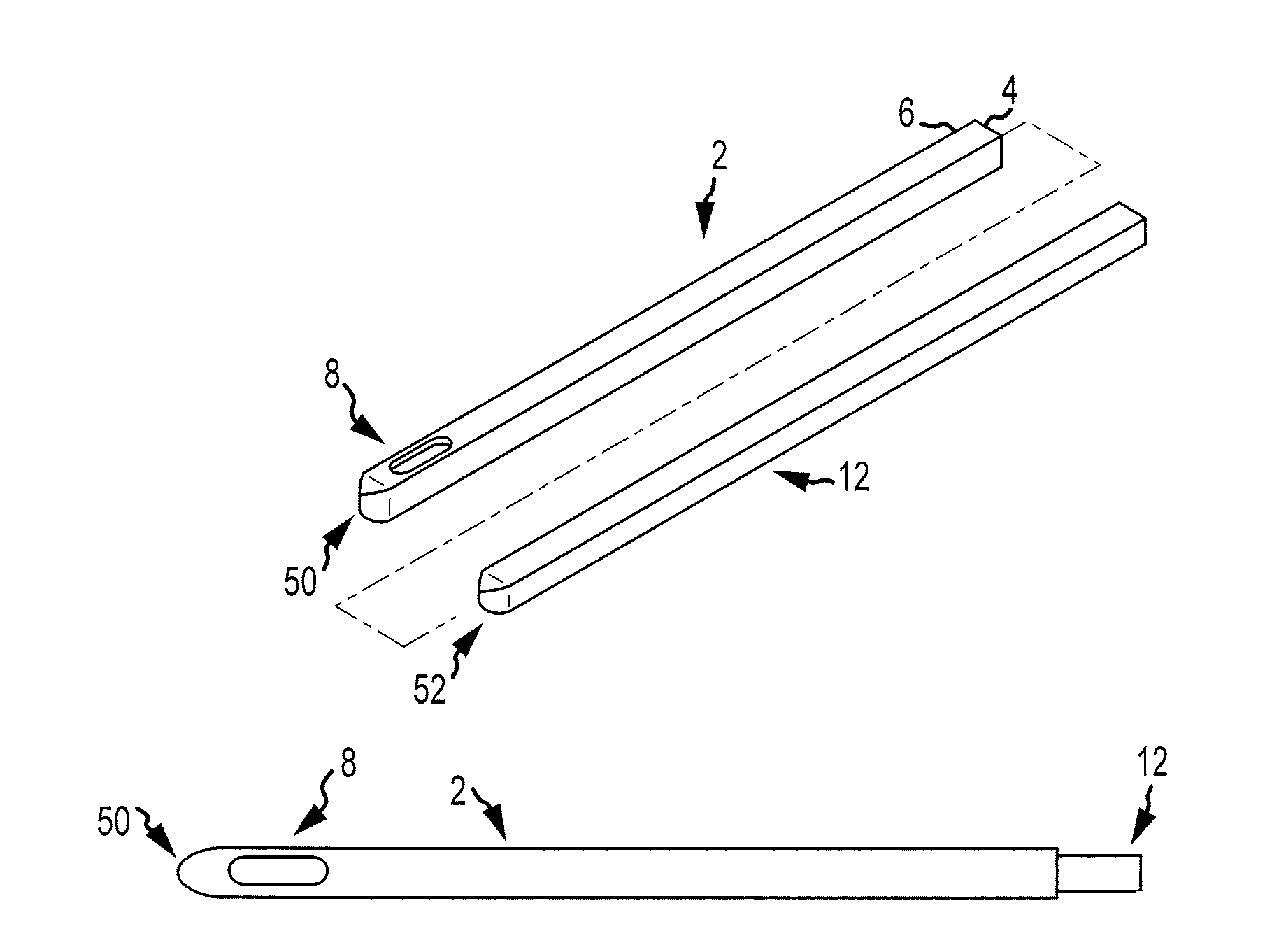
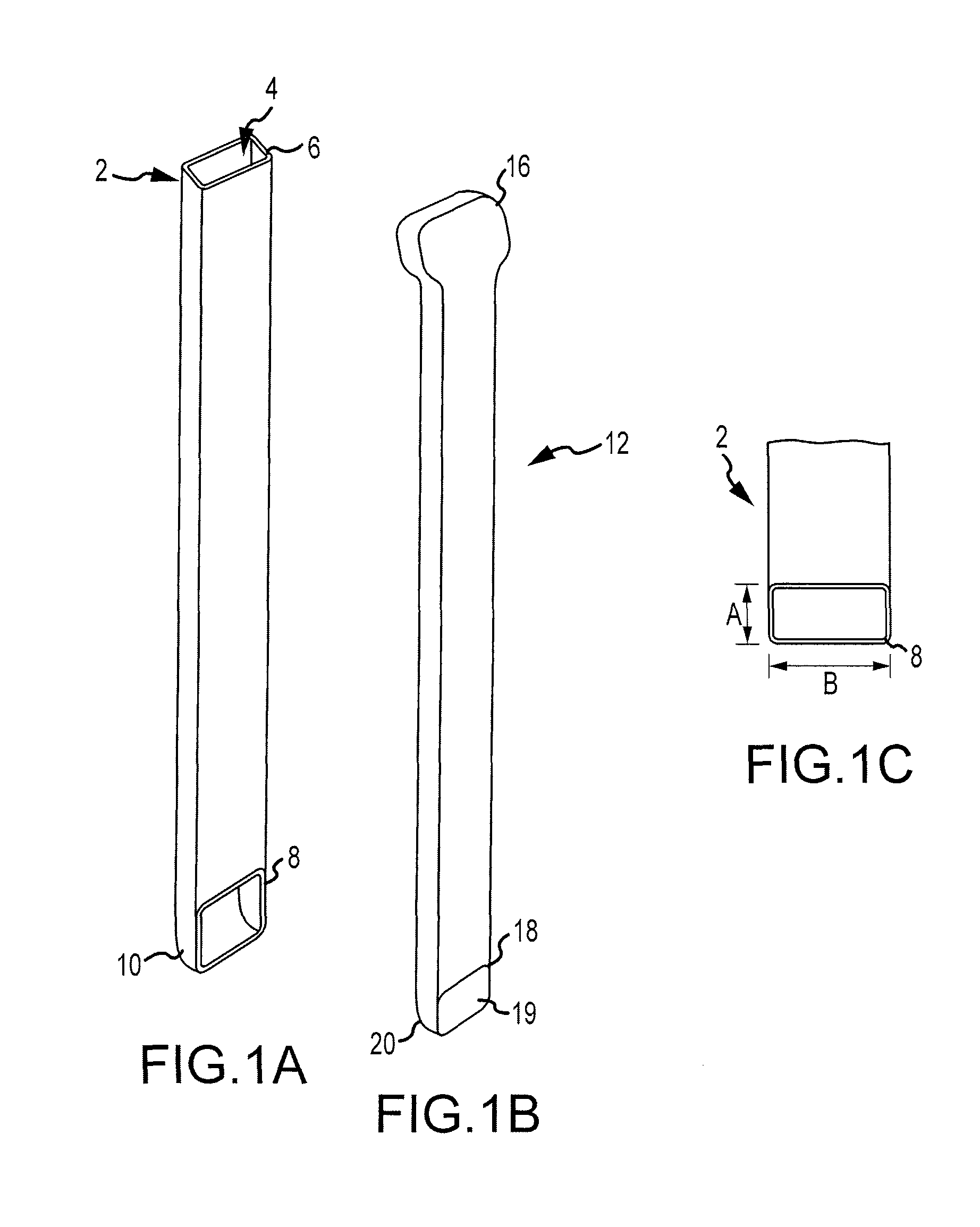
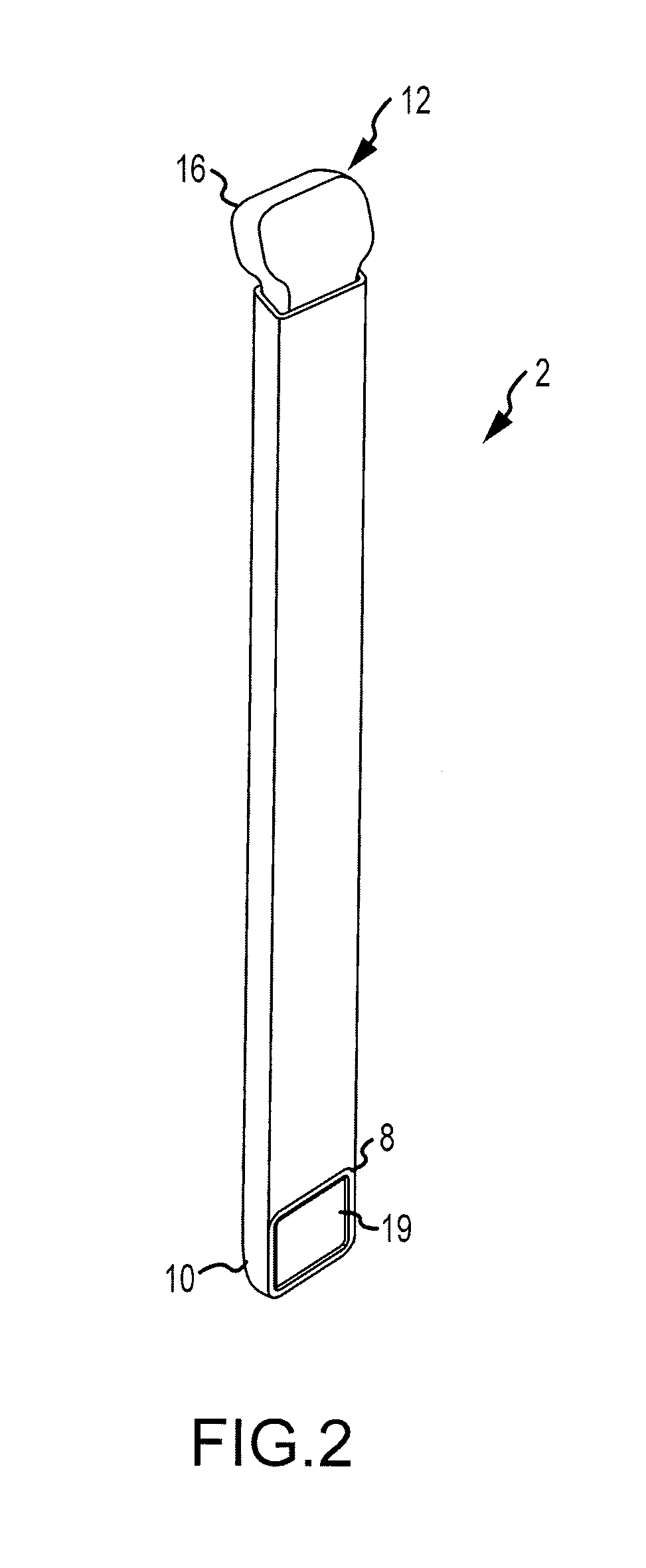
[0057]The present invention relates to a device and method for delivery of bone graft material to any portion of a patient which requires bone graft material. Thus, for example, the foregoing description of the various embodiments contemplates delivery to, for example, a window cut in a bone, where access to such window for bone grafting is difficult to obtain because of orientation of such window, presence of muscle tissue, risk of injury or infection, etc. The bone graft delivery device is formed such that the one or more hollow tubes and / or plungers may be helpful in selectively and controllably placing bone graft material in or adjacent to such window. The bone graft delivery device is formed to allow delivery of bone graft material in a direction other than solely along the longitudinal axis of the device, and in some embodiments transverse to the primary axis used by the surgeon or operator of the device when inserting the device into a cannula or other conduit to access the s...


PUM


Abstract

The present invention relates to a device and method for delivery of bone graft material to any portion of a patient which requires bone graft material. The device according to various embodiments delivers bone graft to a bone graft receiving area. The bone graft delivery device is formed such that a hollow tube and plunger selectively and controllably place bone graft material in or adjacent to the bone graft receiving area.

Description

CROSS REFERENCE TO RELATED APPLICATIONS[0001]This application claims the benefit of U.S. Provisional Patent Application No. 61 / 243,664, filed on Sep. 18, 2009, the entire disclosure of which is incorporated by reference herein.FIELD OF THE INVENTION[0002]This disclosure relates to orthopedic surgery, and more specifically to an apparatus and method for inserting bone graft into a patient.BACKGROUND OF THE INVENTION[0003]Individuals who suffer degenerative disc disease, natural spine deformations, a herniated disc, spine injuries or other spine disorders may require surgery on the affected region to relieve the individual from pain and prevent further injury to the spine and nerves. Spinal surgery may involve removal of damaged joint tissue, insertion of a tissue implant and / or fixation of two or more adjacent vertebral bodies. The surgical procedure will vary depending on the nature and extent of the injury. For a general background on some of these procedures and the tools and appa...

Claims


Application Information

Patent Timeline
Patent Type & Authority Patents(United States)
IPC IPC(8): A61F2/30A61B17/56A61F2/46A61F2/44
CPCA61F2002/30153A61F2002/30601A61F2/4601A61F2/4455A61F2002/4602A61F2230/0019A61B17/8822A61F2/30767A61F2/447A61F2/4611A61F2002/2817A61F2002/2835
Inventor KLEINER, JEFFREYGRIMBERG, JR., EDWARD JOHN
Owner SPINAL SURGICAL STRATEGIES INC A NEVADA CORP D B A KLEINER DEVICE LABS
Why Eureka
Try Eureka