Image capture system for applications in vehicles

a technology for vehicle applications and capture systems, applied in the field of vehicle image capture systems, can solve the problems of large volume of camera systems, inconvenient expansion of baffles, and comparatively large distance between the lower edge of the lens and the windshield, so as to reduce the space requirement, improve the design aspects of the exterior view of the vehicle, and improve the effect of imaging properties

Inactive Publication Date: 2014-12-23
ROBERT BOSCH GMBH
View PDF35 Cites 20 Cited by
  • Summary
  • Abstract
  • Description
  • Claims
  • Application Information

AI Technical Summary

Benefits of technology

[0015]Instead of an air gap between the image capture system and the motor vehicle window pane, this space between the image capture system and the motor vehicle window pane may also be filled by an optical material, i.e. by a material that is transparent for the relevant spectral range. For example, an optical cement may be used for mounting the image capture system on the motor vehicle window pane. This elimination of the air gap would also reliably eliminate disadvantageous effects such as condensation or dirt on the surface of the image capture system or on the relevant region of the motor vehicle window pane.
[0016]The provided image capture system and the provided optical system thus have significant advantages over traditional image capture systems and optical systems in the automotive sector. In addition to the reduced space requirement already described, particularly an improvement of the imaging properties is to be noted as well. This improvement is in particular due to the fact that in all regions of the image capture system light beams now travel a nearly identical path between entering the motor vehicle window pane and striking the image sensors.
[0017]The reduced space requirement also allows for a great reduction in the restriction of the field of view, which results for the driver or the front seat passenger when using the image capture system or the optical system as a forward-directed camera. Furthermore, the see-through window in the motor vehicle window pane is nearly equal in its size as the image sensor itself, i.e. the region of the motor vehicle window pane covered (and thereby “blocked”) by the image capture system is optimally utilized. Design aspects of the exterior view of the vehicle are thereby also significantly improved.
[0018]Regarding the construction and manufacture of the image capture system according to example embodiments of the present invention, reference may largely be made to the above-cited related art. According to example embodiments of the present invention, it is advantageous in this regard if the micro-lenses are situated in at least one lens plane, it being possible for the at least one lens plane and the image plane preferably to be situated essentially in parallel. This parallelism may in particular ensure that the incident light of all micro-lenses is focused on the associated image sensors. Here too, again a slight deviation from the parallelism, for example, a deviation of up to, but no more than, 5° is possible. The thickness of the image capture system, in particular the distance between a lens plane situated farthest on the object side and the at least one image sensor element, advantageously is less than 20 mm, particularly advantageously no more than 10 mm.
[0019]It is furthermore advantageous if the image capture system has an opening angle adapted in particular to the respective field of application. Accordingly, for example, at least one pixel on the edge of the at least one image sensor may have a pick-up direction that deviates by at least 10° with respect to the main viewing direction. Advantageously, a horizontal opening angle is used that is wider than the vertical opening angle of the image capture system. Thus, for example, the maximum deviation of a pick-up direction in a horizontal direction of the at least one image sensor (half opening angle horizontally) may be between 5° and 50°, preferably between 10° and 40°, and in a vertical direction of the at least one image sensor (half opening angle vertically) between 2° and 40°, preferably between 5° (telephoto-like construction) and 20°.
[0020]In accordance with the related art, for example, conventional CCD chips or other image sensor elements may be used as image sensor elements. These may be used such, for example, that each of the image sensors (pixels) of the image sensor element is assigned one or more micro-lenses (complete utilization) or, less preferably, only a certain number of the image sensors may be used, other image sensors of the image sensor element remaining unused.

Problems solved by technology

Since a lens of the camera system for capturing the area in front of the motor vehicle must be oriented horizontally, however, there is a comparatively large distance between the lower edge of the lens and the windshield, while the upper edge of the lens is often almost flush with the windshield.
One disadvantage, for example, is the fact that such camera systems having baffles on the whole have a large volume, while only a small space of this built-up volume is actually used.
In addition, the expansive baffles are also not desirable from the standpoint of design.
Another disadvantage is the fact that the region of the window pane (see-through window), which must be reserved for the camera system, must be dimensioned relatively large because of the comparatively large distance between the camera lens system and the window pane, particularly if the camera is designed for a large horizontal capturing range.
In this instance, however, the problem continues to exist that the conventional image capture systems, when used behind sloped window panes, in particular behind the described windshields, would have to exhibit an increasing distance from the windshield in the downward direction in order to monitor the region ahead of the motor vehicle.

Method used


Image

  • Image capture system for applications in vehicles
  • Image capture system for applications in vehicles
  • Image capture system for applications in vehicles

Examples


Embodiment Construction

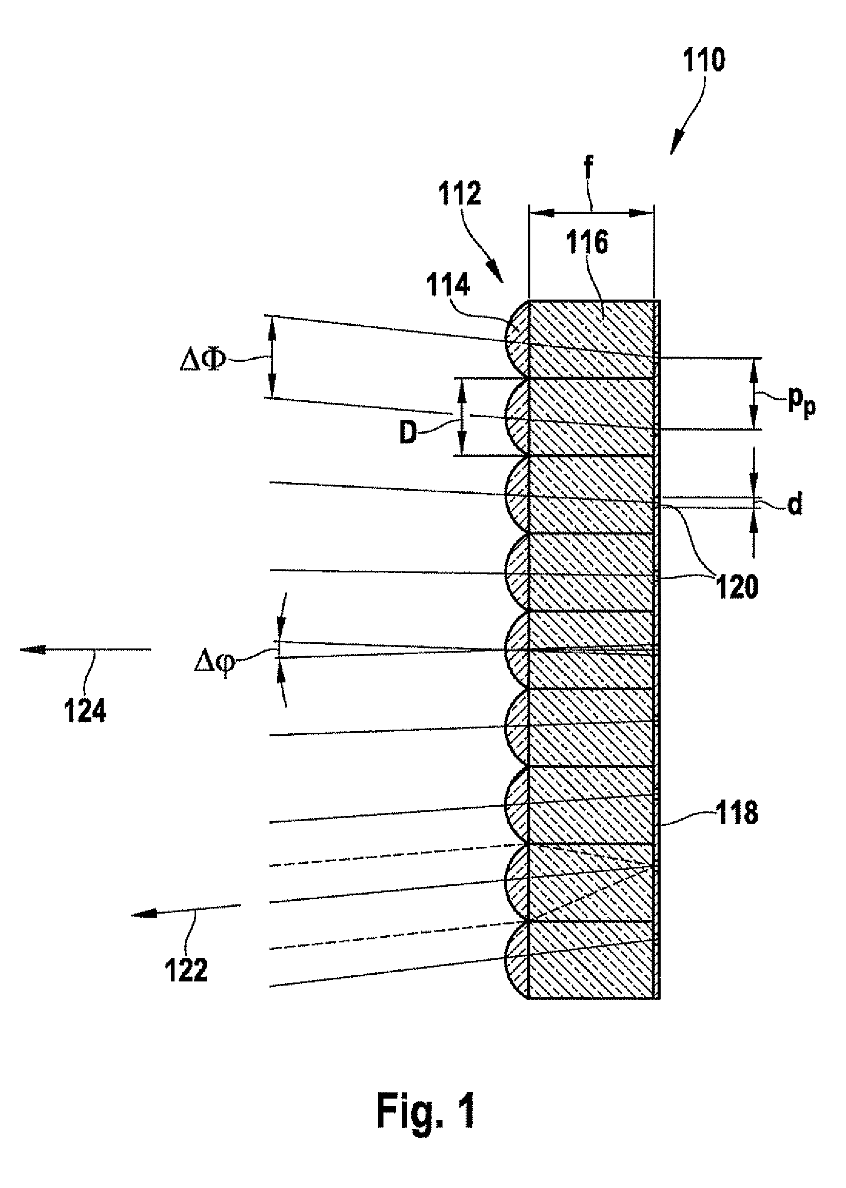
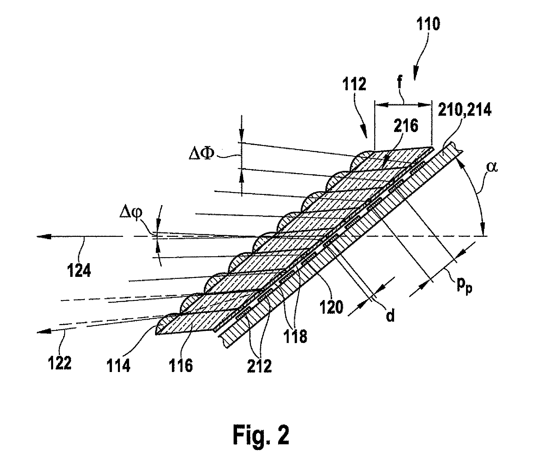
[0026]FIG. 1 shows a part of a conventional image capture system 110, the structure and manufacture of which is described, for example, in the above-cited publication by J. Duparre et al. in Applied Optics. Image capture system 110 has a micro-lens system 112 having a plurality of micro-lenses 114 arranged to form a matrix. Each micro-lens 114 has an associated pillar 116 of an optical material, the pillar in this case being a vertical pillar.

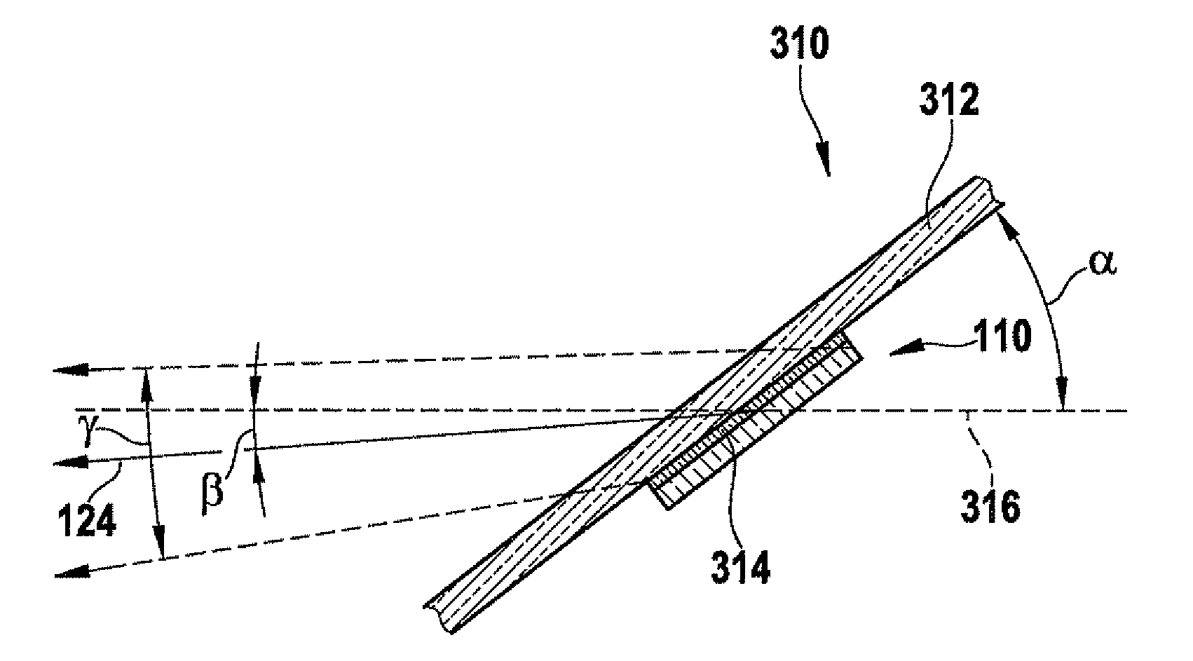
[0027]Furthermore, an aperture mask 118 is provided, which in this exemplary embodiment is situated directly adjacent to pillars 116. Aperture mask 118 has a plurality of openings 120, one opening 120 being respectively associated with one micro-lens 114. Thus one micro-lens 114 and one opening 120 respectively define a pick-up direction 122 of a pixel. In this example, pick-up direction 122 of the central pixel or central opening 120 defines main viewing direction 124 of image capture system 110. In this image capture system 110, main viewing ...


PUM


Abstract

In an image capture system for use in vehicles as well as an optical system for use in the automotive sector, the image capture system has at least one image sensor element having a plurality of image sensors situated in an image plane and at least one micro-lens system having a plurality of micro-lenses. Optionally, at least one aperture mask having a plurality of openings is situated between the micro-lens system and the at least one image sensor element. One image sensor, one micro-lens and one opening respectively define a pick-up direction of the image sensor. The totality of the pick-up directions defines a main viewing direction, which together with the image plane encloses an angle α of less than 80°.

Description

FIELD OF THE INVENTION[0001]The present invention relates to an image capture system for applications in vehicles.BACKGROUND INFORMATION[0002]In modern motor vehicles, camera systems are already used today to monitor and / or capture the interior and / or exterior areas. Thus, for example, camera systems in the interior are used for monitoring occupants of the vehicle, for example, so as to be able to control safety systems in accordance with an occupancy of the seats and / or a current posture of the vehicle's occupants. Camera systems for the exterior are used, for example, as backup aids or also for capturing an area ahead of the motor vehicle, for example.[0003]Such camera systems, in particular camera systems for capturing the area ahead of the motor vehicle are usefully mounted behind a vehicle window pane, for example a windshield, so as to protect particularly the sensitive sensor system of the camera systems against the extreme environmental impacts to which a motor vehicle is ex...

Claims


Application Information

Patent Timeline
Patent Type & Authority Patents(United States)
IPC IPC(8): G02B3/00H04N5/225H04N7/18
CPCH04N5/2254H04N5/2252G02B3/0056H01L27/14627H04N23/51
Inventor SEGER, ULRICHAPEL, UWEHOELLT, CHRISTIAN
Owner ROBERT BOSCH GMBH
Why Eureka
Try Eureka