Method for three-dimensionally bending workpiece and bent product

a three-dimensional bending and workpiece technology, applied in the direction of shaping tools, forging/pressing/hammering apparatuses, heating/cooling devices, etc., can solve the problems of difficult to prevent the occurrence of uneven distortion, the quenching accuracy cannot be guaranteed, and the cooling speed cannot be accurately controlled. achieve the effect of high degree of operation efficiency, high degree of bending accuracy, and high strength

Active Publication Date: 2014-12-30
NIPPON STEEL CORP
View PDF46 Cites 13 Cited by
  • Summary
  • Abstract
  • Description
  • Claims
  • Application Information

AI Technical Summary

Benefits of technology

[0010]As described above, a technique for bending a metal material in various bending shapes to be applied to various parts of an automobile is demanded in association with reassessing the structures of the parts of an automobile. Meanwhile, it is desirable that the metal material have a tensile strength of 900 MPa or more, preferably, 1300 MPa or more, in order to reduce the weight of the metal material. In this case, a metal tube having a tensile strength of about 500 to 700 MPa is bent as a starting material and a thermal treatment is performed on the bent metal tube to improve the strength of the metal tube, thereby obtaining a metal material having high strength.
[0012]The invention is designed to solve the above-mentioned problems, and it is an object of the present invention to provide a method for bending a metal material with a high degree of operation efficiency, while the method allowing a high degree of bending accuracy to be ensured even when a metal material is bent in various shapes in association with diversification of structures of automobile parts and further even when a metal material having high strength is bent likewise.
[0014]That is, in the bending of a metal material, the downstream side of the metal material is supported, and a thermal treatment is performed on the metal material while moving the metal material at a predetermined speed, which makes it possible to ensure a predetermined cooling speed. In addition, since the bent metal material is uniformly cooled down, it is possible to obtain a metal material having excellent shape fixability despite high strength, and uniform hardness.
[0016]According to a second aspect of the present invention, preferably the temperature range of step (b) is over the A3 transformation point of the metal material of the workpiece. More preferably, the cooling rate is more than 100° C. / sec in step (d). Further, preferably, the local part of the workpiece to be heated is with a length-wise width of within 30 mm in the axial direction. When the temperature range, the cooling rate and the local part width of the workpiece are controlled, the quenching performance of the workpiece become stable and it is easy to obtain a metal material having excellent shape fixability despite having high strength, and uniform hardness distribution at a low cost.
[0017]In this way, the bending method according to the present invention can be widely applied as an art of accurately bending automobile parts.

Problems solved by technology

However, in the grab bending method disclosed in Japanese Patent Application Publication No. 50-59263 and Japanese Patent No. 2816000, since the feeding speed of the metal tube varies significantly, the cooling speed cannot be accurately controlled, and a high degree of quenching accuracy cannot be ensured, which makes it difficult to prevent the occurrence of uneven distortion.
Thus, products made by the grab bending method are not suitable for parts of an automobile.

Method used


Image

  • Method for three-dimensionally bending workpiece and bent product
  • Method for three-dimensionally bending workpiece and bent product
  • Method for three-dimensionally bending workpiece and bent product

Examples


Embodiment Construction

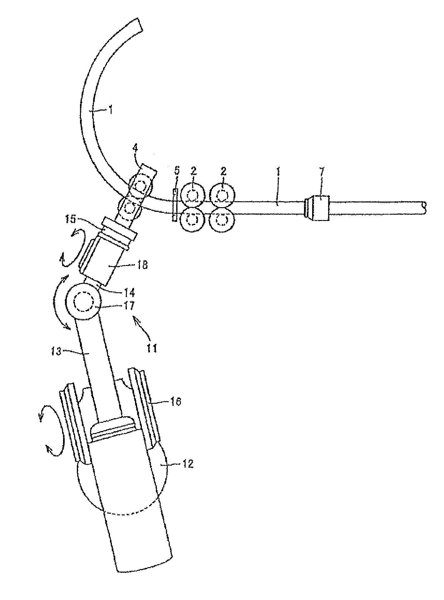
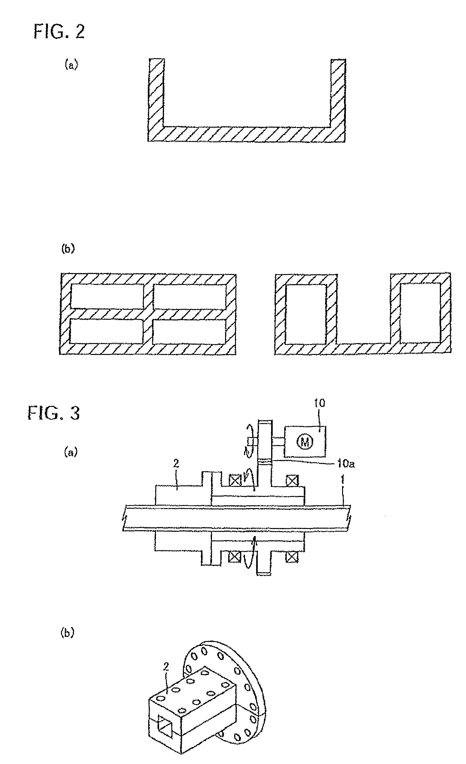
[0030]Hereinafter, in light of an overall structure of a three-dimensionally bending machine, an example of the structure of a supporting unit, the structure of a processing section and examples of the structures of heating and cooling units, the structure of a movable unit (comprising rolls as roller-dies), the operation of a preheating unit, and the structure and layout of an articulated robot, the method using the three-dimensionally bending machine according to exemplary embodiments of the present invention will be described with reference to the accompanying drawings.

[0031]1. Overall Structure of Three-Dimensionally Bending Machine and Example of Structure of Supporting Unit

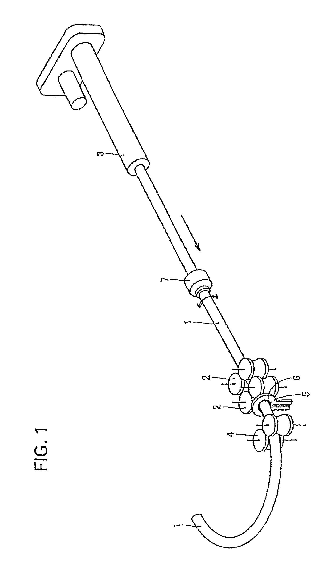
[0032]FIG. 1 is a diagram illustrating the overall structure of a three-dimensionally bending machine for applying a bending method of the present invention. In the bending method, a workpiece 1 as a starting material that is rotatably supported by a supporting unit 2, is successively or continuously fed fro...


PUM

PropertyMeasurementUnit
widthaaaaaaaaaa
tensile strengthaaaaaaaaaa

Abstract

A method for three-dimensionally bending a workpiece comprises feeding the workpiece by a feeding unit provided at an upstream side of the workpiece, supporting the workpiece by a supporting unit at a downstream side of the feeding unit, processing the workpiece by clamping the workpiece with a three-dimensionally movable unit that is provided downstream of the supporting unit, heating a local part of the workpiece in a temperature range which allows quenching to be performed, applying a bending moment to the heated local part of the workpiece by the three-dimensionally movable unit in association with the supporting position and / or the moving speed of the workpiece after the heating step, and rapidly quenching the heated portion. Even when a high-strength workpiece is bent, it is possible to effectively obtain a product having excellent shape fixability and uniform hardness distribution at low costs for wide application for bending sophisticated automobile parts.

Description

[0001]This is a continuation-in-part of U.S. application Ser. No. 11 / 896,319 filed Aug. 31, 2007 now abandoned, which is a continuation of PCT / JP2006 / 1303220 filed Feb. 23, 2006. The PCT application was not in English as published under PCT Article 21(2).TECHNICAL FIELD[0002]The present invention relates to a method for bending a workpiece, and more particularly, to a method for effectively bending a workpiece through a three-dimensional continuous bending operation in which the workpiece is three-dimensionally bent in different directions, and to a bent product made by the bending method.BACKGROUND ART[0003]In recent years, demands for structural metal materials having high strength and light weight have increased in consideration of global environment. For example, in an automobile industry, there are growing demands for the safety of car body, and high-strength and light-weight parts of an automobile are increasingly required, so that parts of an automobile have been developed in...

Claims


Application Information

Patent Timeline
Patent Type & Authority Patents(United States)
IPC IPC(8): B21D7/16B21D7/08B21D7/04
CPCB21D7/08B21D7/16B21D11/10B21B1/00B21D35/002B21D43/006Y10T428/1241
Inventor TOMIZAWA, ATSUSHIKIKUCHI, FUMIHIKOKUWAYAMA, SHINJIRO
Owner NIPPON STEEL CORP
Why Eureka
Try Eureka