Cartridge piston

a cartridge and piston technology, applied in the direction of liquid transfer devices, instruments, volume meters, etc., can solve the problems of unsuitable sealing lip, unsuitable piston for fillings containing solids discharge, and unsuitable piston for discharge of known fillings, etc., to achieve the effect of improving the guidance of the piston

Active Publication Date: 2014-12-30
MEDMIX SWITZERLAND AG
View PDF15 Cites 105 Cited by
  • Summary
  • Abstract
  • Description
  • Claims
  • Application Information

AI Technical Summary

Benefits of technology

[0026]Stiffening ribs can be arranged on the drive side of the piston. The provision of stiffening ribs ensures that the piston remains inherently stable even if the piston is put under pressure by means of a discharge device on the discharge of the filling.
[0027]A tilt securing element can be arranged on the drive side of the piston and serves for the improvement of the guidance of the piston in a cartridge. The piston is guided securely against tilting by the tilt securing element which is in contact with the wall of the cartridge, thus the axis of the piston body coincides with the piston axis. The tilt securing element ensures that th

Problems solved by technology

However, such a piston may only be compatible with limitations with materials which form the filling of the cartridge.
However, these already known pistons have proved to be unsuitable for the discharge of fillings containing solids.
However, such a sealing lip is not suitable for a practical application since the lip is easily damaged on the introduction of the piston into the cartridge.
However, the piston of CH 610 9

Method used


Image

  • Cartridge piston
  • Cartridge piston
  • Cartridge piston

Examples


Embodiment Construction

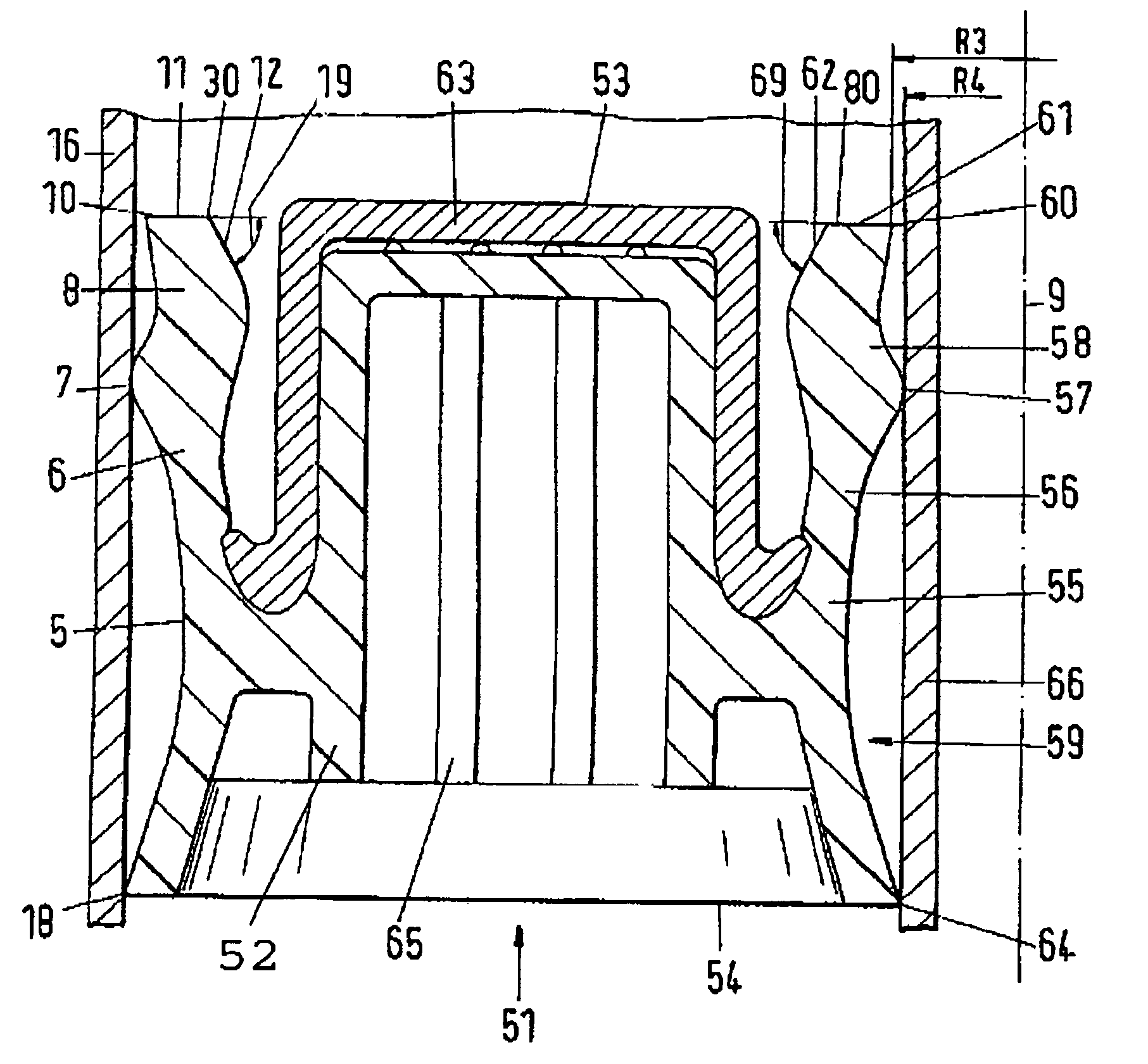
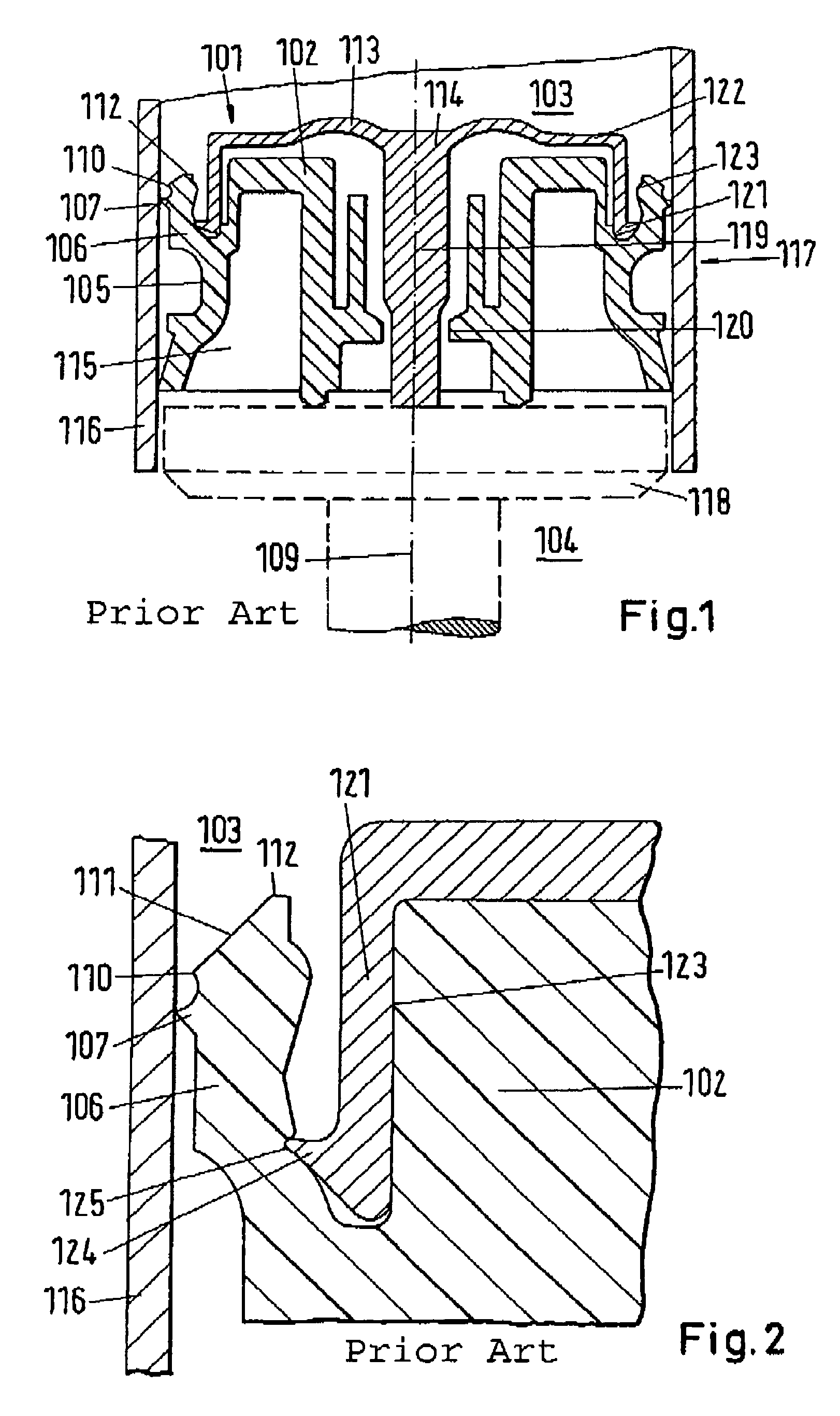
[0041]Referring to FIG. 1, a piston 101, as is known from the prior art, includes a piston body 102 which is usually manufactured by means of an injection molding process from plastic. The piston 101 is preferably used to discharge a filling, in particular of fluid or pasty media, from a cartridge. A wall 116 of the cartridge 117 is shown. The piston 101 slides along the wall 116 and, during this movement, pushes the filling through a discharge opening (not shown). The side of the piston 101 at the media side is defined as the conveying side 103 in the following. To set the piston into motion and to keep the piston in motion, a compressive force is applied by means of a discharge device. The discharge device, of which a plunger element 118 is shown, is located on the side of the piston which is disposed opposite the conveying side 103. This side is defined as the drive side 104 in the following.

[0042]“The piston body 102 is thus bounded by the drive side 104, the conveying side 103 ...


PUM


Abstract

The piston includes a piston body having a conveying side, an oppositely disposed drive side and, at the circumferential side, a piston jacket forming a connection between the conveying side and the drive side. The piston jacket has a projection that carries a guide element for the guidance of the piston in a cartridge containing a filling with solid particles and for forming a sealing contact with a wall of the cartridge. The projection also carries a scraper element in front of the guide element for scraping solid particles from the cartridge wall back into the filling during discharge.

Description

FIELD OF THE INVENTION[0001]This invention relates to a piston for a cartridge, in particular for the discharge of fillings containing solids. More particularly, this invention relates to a piston for a cartridge for dispensing a multicomponent mixture.BACKGROUND OF THE INVENTION[0002]Pistons for cartridges for dispensing a multicomponent mixture are known, for example, from DE 200 10 417 U1, wherein the piston has a first piston part which is provided with a sealing lip that contacts the cartridge wall.[0003]Another piston is disclosed in EP 1 165 400 B1 wherein the piston is made up of a soft plastic, for example LDPE (low density polyethylene) in order to achieve the required sealing effect toward the cartridge wall. However, such a piston may only be compatible with limitations with materials which form the filling of the cartridge. To avoid the piston coming into contact with such materials along its conveying side, a cover plate is used which is made of a plastic which is resi...

Claims


Application Information

Patent Timeline
IPC IPC(8): B65D88/54
CPCB05C17/00576B65D83/0005B05C17/00579B05C17/005B65D83/00
Inventor OBRIST, MANFRED
Owner MEDMIX SWITZERLAND AG
Why Eureka
Try Eureka