Weapon sight light emission system

a technology of light emission system and weapon sight, which is applied in the direction of weapon components, sighting devices, weapons, etc., can solve the problems of reducing affecting the accuracy of aiming the weapon, and affecting the installation of the light gathering element and the light emitting element in the proper dimensional relation to achieve the brightness of the aiming indicia

Active Publication Date: 2015-01-06
HIVIZ LLC
View PDF65 Cites 16 Cited by
  • Summary
  • Abstract
  • Description
  • Claims
  • Application Information

AI Technical Summary

Benefits of technology

[0010]Accordingly, a broad object of the invention can be to provide various embodiments of a light emission assembly useful in weapon sights to provide an illuminated sight regardless of the ambient light conditions. The light emission assembly can include a light conductive member produced from light conductive material which receives light on the external surface and transmits the light to a viewable end. The light conductive member can further include a chamber in which a light emitting element can be located to emit light toward the viewable end of the light emission assembly. The light emission assembly can further provide a lens configured to define one illumination field over which the light transmitted by the light conductive material and the emitted light of the light emitting element can spread to provide a viewable aiming indicia having substantially uniform area regardless of the ambient light conditions.

Problems solved by technology

However, there are certain disadvantages with these types of conventional weapon sights in that the installation of the light gathering element and the light emitting element in proper dimensional relation to achieve sufficient brightness of the aiming indicia can be difficult.
In some cases, the light gathering element or the light emitting element can migrate due to a failure in whole or in part of the means for attaching these components to the weapon sight, such as a failure of adhesive.
Moreover, conventional light gathering elements can have an overall length which acts to reduce the field of illumination of the aiming indicia which in turn can reduce accuracy in aiming the weapon.
The longer the fiber the greater the attenuation losses, due to transmissivity, refraction, and reflection of light.
The shortened sight radius can have a detrimental effect on accuracy of aiming the weapon.
Moreover, the longer length of conventional light gathering elements can mechanically interfere with holstering the weapon or use of the weapon with other weapon paraphernalia.

Method used


Image

  • Weapon sight light emission system
  • Weapon sight light emission system
  • Weapon sight light emission system

Examples


Embodiment Construction

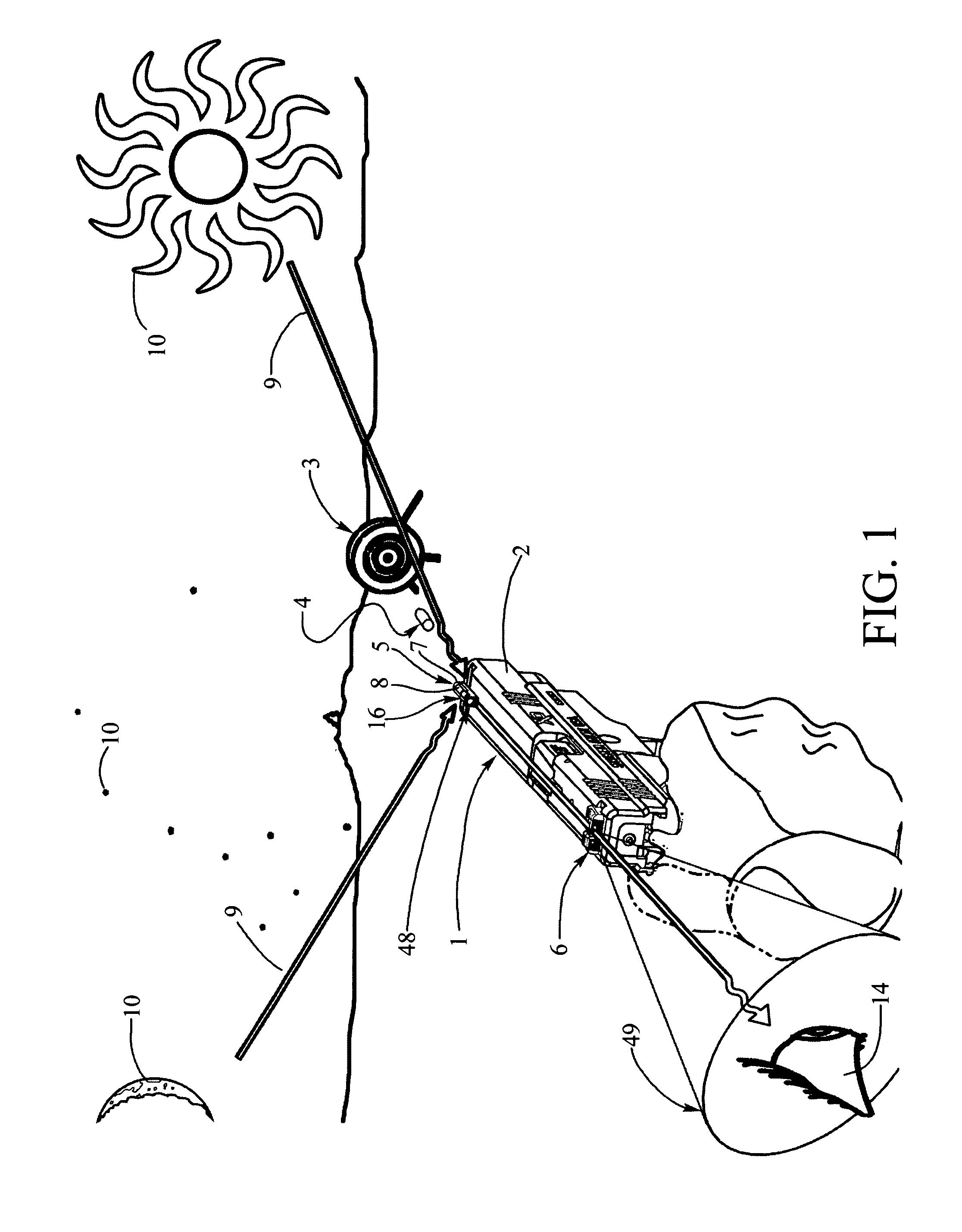
[0072]Now referring primarily to FIG. 1, which illustrates a method of using a particular embodiment of the inventive weapon sight (1) which may be adapted for use with a numerous and wide variety of weapons (2) to aim the weapon to direct energy, project beams, launch projectiles (such as bullets, pellets, BBs), or the like whether each individually or in various combinations (individually or collectively “projectile(s)”) (4) at a target (3). The weapons (2) to which the inventive weapon sight (1) can be adapted include, without limitation, hand guns, rifles, bows, shot guns, BB guns, pellet guns, laser weapons, energy weapons, or the like. The term “weapon” (2) is not intended to be limiting, but rather to broadly encompass devices which can be aimed for military, sporting, hobby or other applications. The target (3) may be any object at which the weapon (2) can be aimed to receive the projectile(s) (4), including, inanimate and animate objects.

[0073]Again referring primarily to F...


PUM


Abstract

A light emission assembly for weapon sights which provides a viewable illuminated aiming indicia of substantially fixed area and uniform brightness regardless of the ambient light conditions.

Description

[0001]This U.S. Non-provisional patent application claims the benefit of U.S. Provisional Patent Application No. 61 / 459,749, filed Dec. 17, 2010, incorporated by reference herein.I. BACKGROUND[0002]A light emission assembly for weapon sights which provides a viewable illuminated aiming indicia of substantially fixed area and uniform brightness regardless of the ambient light conditions.[0003]Certain conventional weapon sights use light gathering elements such as optical fiber(s), fluorescent fibers, or the like, to transmit ambient light to one or both ends to provide an aiming indicia useful in aiming a weapon. Improvements have been made over time to locate an artificial light source (such as tritium gas-filled, thin glass capsules whose inner surfaces are coated with a phosphor, light emitting diodes, or like) adjacent the external surfaces of the light gathering fibers to provide an aiming indicia useful in aiming the weapon even in low ambient light or darkness. For example, U....

Claims


Application Information

Patent Timeline
Patent Type & Authority Patents(United States)
IPC IPC(8): F41G1/00F41G1/34
CPCF41G1/345
Inventor HOWE, PHILLIP D.MOORE, RICHARD A.HERNDON, RICHARD K.
Owner HIVIZ LLC
Why Eureka
Try Eureka