Low torque and vacuum seed meter

a vacuum and seed meter technology, applied in the field of seed disk rotation mounting arrangement and air sealing assembly, can solve the problems of complex array of flexible fingers and difficult to achieve, and achieve the effects of low power consumption, improved uniform seed placement, and high efficiency

Active Publication Date: 2015-01-06
BLUE LEAF I P INC
View PDF9 Cites 47 Cited by
  • Summary
  • Abstract
  • Description
  • Claims
  • Application Information

AI Technical Summary

Benefits of technology

[0004]The present invention is directed to a seed meter which provides improved uniformity of seed placement during row crop planting and that is highly efficient so as to require relatively little power to operate when compared to less efficient seed meters. The seed meter may include a seed disk that is supported for low-drag rotation about a spindle by way of bearing assemblies. The seed disk may, itself, be connected to a seed disk hub in which the bearing assemblies are concentrically mounted for rotation about the spindle. The seed disk may be sealed at its outer periphery to the seed disk hub so that a space is provided between the seed disk and a back wall of the seed disk hub. A vacuum may be drawn through the center of the seed disk hub to create negative pressure in the space between the seed disk and seed disk hub back wall, for drawing seeds against the seed disk. In this way, the negative pressure of the seed meter is created within a rotating unitary seed disk assembly that is defined by the seed disk and the seed disc hub, which eliminates the seed disk from being drawn by vacuum against a stationary housing or other component of the seed meter. The fully sealed unit of the seed disk assembly may require relatively less input vacuum pressure to achieve sufficient vacuum pressure at each of multiple seed disk cells into which the seeds are drawn for being dispensed from the seed meter when compared to typical seed meters that have pressure differentials that are established across rotating components that engage fixed components of the seed meter, such as a seed disk and a fixed seed cover. The invention may therefore provide more efficient rotating assemblies that require less torque for rotating the seed disks and require less vacuum pressure to draw seeds against the seed disks so that the seed meters can be operated while using less power.
[0005]According to one aspect of the invention, a seed meter is provided that includes a housing assembly that includes a housing cavity therein and a seed disk assembly that is arranged for rotation inside of the housing cavity. The seed disk assembly includes a support plate that has a back wall and a seed disk that is mounted to the support plate so that the support plate back wall and seed disk are spaced from each other. A seed disk assembly cavity is defined in the space between the support plate back wall and seed disk. A wiper seal is arranged within the seed disk assembly cavity. The wiper seal extends between and engages each of the support plate back wall and the seed disk. This creates a sealed-off section of the seed disk assembly cavity so as to define a vacuum zone and a non-vacuum zone in the seed disk assembly cavity. In the vacuum zone, a vacuum pressure within the seed disk assembly pulls and holds seeds into openings in the seed disk. The non-vacuum zone may define a cutoff chamber such that in the non-vacuum zones, the seed disk assembly is at ambient or greater pressure, whereby the seeds are not held against the seed disk by vacuum pressure and the seeds can freely fall away from the seed disk to be deposited into a seed bed. By substantially confining the vacuum pressure between the seed disk and support plate that rotate in unison with each other, a frictional braking force between the seed disk and a fixed housing component may be avoided and the seed disc can be rotated with relatively less torque. The torque required to rotate the seed disk assembly may correspond to an amount needed to overcome frictional engagement of the wiper seal and the inwardly facing surfaces of the seed disk assembly.
[0006]According to another aspect of the invention, the housing assembly includes a spindle that is hollow and connected to a vacuum source and that extends inwardly into the housing cavity. The seed disk assembly may be mounted for rotation with respect to and operably connected to the spindle so that a vacuum airflow that is created by the vacuum source is drawn from the vacuum zone of the seed disk assembly and through the spindle of the housing assembly. This may provide a relatively low volume sealed rotating assembly in which the vacuum pressure is created in the seed meter which may require less power to create sufficient vacuum pressure to hold seed against the seed disk.
[0007]According to another aspect of the invention, the wiper seal is fixed with respect to the spindle so that the seed disk assembly slides across the wiper seal when the seed disk assembly rotates. The wiper seal may include a pair of opposing side edges that engage the seed disk assembly support plate and seed disk, and an end edge that engages a collar that extends from the support plate. The wiper seal may include a first segment that extends through the seed disk assembly cavity generally radially in a first direction and a second segment that extends through the seed disk assembly cavity generally radially in a second direction that is different from the first. The first and second segments of the wiper seal assembly define an angle of greater than about 90 degrees therebetween. The wiper seal may include a third segment that extends between and connects the first and second segments to each other, and the third segment may be arcuate and have a curvature that corresponds to an outer circumferential surface of the spindle. This may allow the wiper seal to seal off a relatively large portion of the seed disk assembly cavity, for example, at least about 25 percent, which may allow seeds to gravitationally fall away from the seed plate without requiring ancillary mechanical seed removal devices.
[0008]According to another aspect of the invention, an inner bracket may be arranged and fixed within the seed disk assembly cavity. The inner bracket may support the wiper seal from a position that is relatively nearer a central axis of the cavity than the wiper seal. An outer bracket may be arranged and fixed within the seed disk assembly cavity, and that supports the wiper seal from a position that is relatively further from the central axis of the cavity than the wiper seal. The wiper seal may be sandwiched between the inner and outer brackets engaging surfaces of the brackets that face toward each other. This may allow the wiper seal to be made from a relatively resilient material that provides a low frictional engagement with the support plate back wall and seed plate while being supported with sufficient rigidity so that the wiper seal does not buckle under the vacuum pressure influence and thus the seal integrity between the vacuum and non-vacuum zones can be maintained.
[0009]According to another aspect of the invention, the inner bracket may be mounted to the spindle and may include an opening that fluidly communicates with an opening of the spindle so that a vacuum airflow can be directed through the inner bracket and the spindle. In this way, the opening of the inner bracket faces toward the vacuum zone and may face radially, away from the spindle. The opening may be defined at an open, side of the inner bracket that has an elongate opening defined between a pair of side plates. The inner bracket may include a closed side that is defined by a solid wiper seal support wall that extends between the side plates and to which the wiper seal is mounted. The seal support wall may face toward the non-vacuum zone. This may provide a simple arrangement for separating the seed disk assembly into vacuum and non-vacuum zones while fixing the wiper seal so that is does not rotate but instead maintains a fixed position within the seed disk assembly cavity while support plate and seed disk rotate past the wiper seal.

Problems solved by technology

This can be especially difficult to accomplish during planting and seeding operations that require precise seed depth placement and spacing accuracy in order to maintain a good seed environment.
Such seed meters apply a vacuum pressure to the entire inside space of the rotating vacuum chamber and require a complex array of numerous flexible fingers.

Method used


Image

  • Low torque and vacuum seed meter
  • Low torque and vacuum seed meter
  • Low torque and vacuum seed meter

Examples


Embodiment Construction

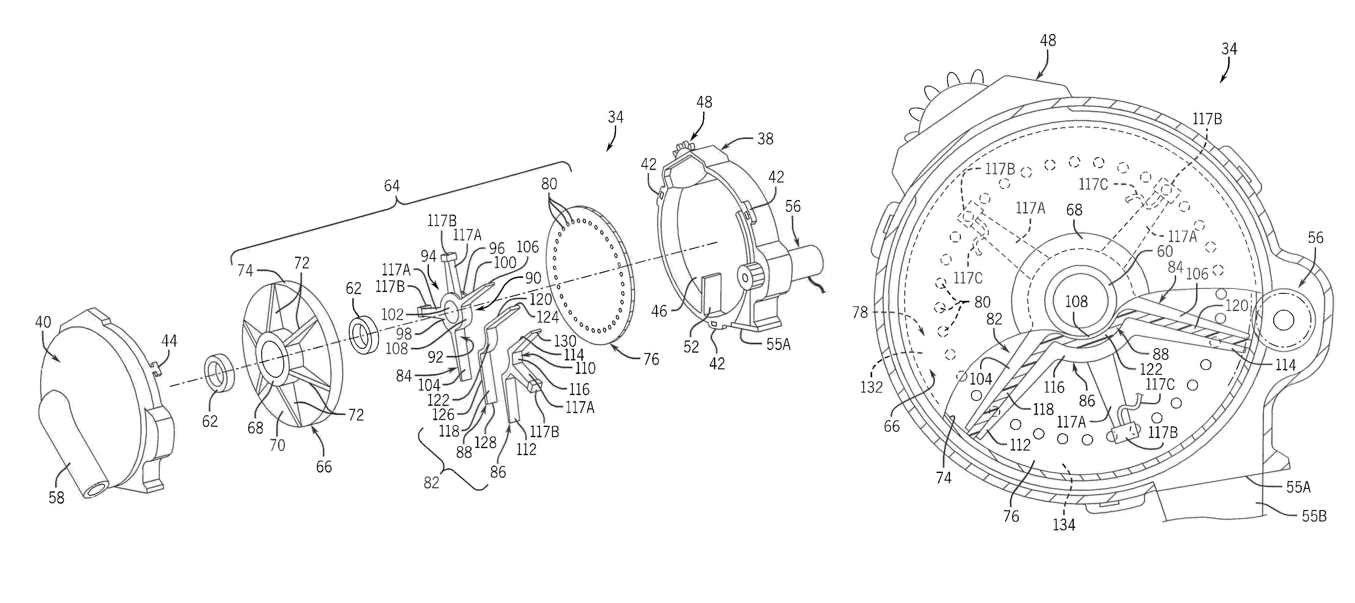
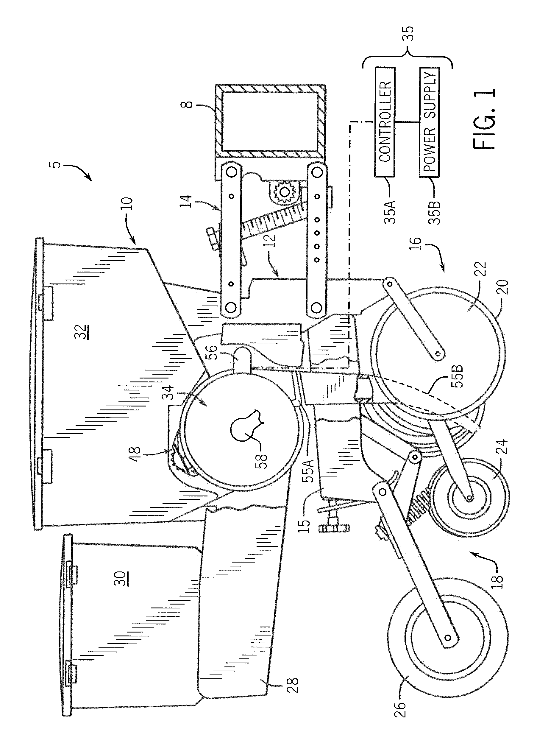
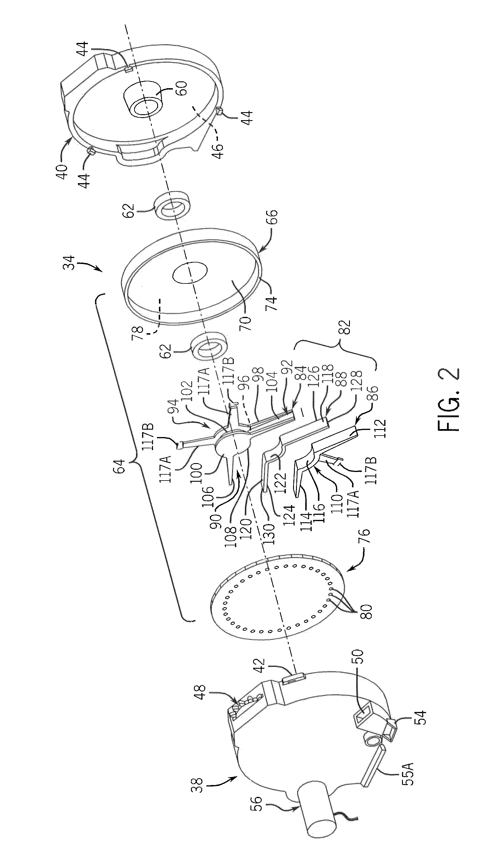
[0018]Referring now to the drawings and specifically to FIG. 1, a portion of a multiple row crop planter implement or seed planter 5 is shown. The seed planter 5 is typically pulled by a tractor or other traction device (not shown). Seed planter 5 includes a main frame 8 that holds multiple individual row planting units 10, each row planting unit 10 being substantially identical. Only a single row planting unit 10 is shown for simplicity sake.

[0019]Still referring to FIG. 1, row planting unit 10 includes a sub-frame 12 that is connected to the main frame 8 by way of a parallel linkage system 14. The sub-frame 12 includes a backbone 15 that supports a furrow opening mechanism 16 and a furrow closing mechanism 18 that is arranged behind the furrow opening mechanism 16. The furrow opening mechanism 16 includes an opener disk(s) 20 that penetrates the soil and creates a furrow and gauge wheel 22 that has a limited displacement relative to the opener disk(s) 20. This allows the depth of ...


PUM


Abstract

A seed meter is provided for use with a row crop planter or seed planter that includes a seed disk assembly that rotates within a meter housing cavity and that has a seed disk assembly cavity in which a vacuum pressure is applied for pulling seeds into seed pockets of a seed disk of the seed disc assembly. The vacuum pressure is applied to the seed disk assembly by pulling a vacuum airflow through a spindle that supports the seed disk assembly. A wiper seal is arranged in a fixed position within the seed disk assembly cavity and seals against the seed disk assembly as a support plate and seed disk of the seed disk assembly rotate over the wiper seal, so that the wiper seal creates a boundary between a vacuum zone and a non-vacuum zone inside of the seed disc assembly cavity.

Description

FIELD OF THE INVENTION[0001]The invention relates generally to row-crop planters or seeders and, in particular, to seed disk rotational mounting arrangements and air sealing assemblies for seed meters.BACKGROUND OF THE INVENTION[0002]Modern farming practices strive to minimize operating expenses. One way of reducing operating expenses is to operate the farm equipment at relatively faster speeds, which reduces the amount of operating time to complete certain tasks. When operating equipment at faster speeds, it can be important to maintain the quality of operation that can be achieved while operating at relatively slower operating speeds. This can be especially difficult to accomplish during planting and seeding operations that require precise seed depth placement and spacing accuracy in order to maintain a good seed environment. Accordingly, seed meter functionality can be very important in modern farming practices to obtain profitability.[0003]Another way of reducing operating expen...

Claims


Application Information

Patent Timeline
Patent Type & Authority Patents(United States)
IPC IPC(8): A01C7/16
CPCA01C7/046
Inventor ADAMS, BRIAN T.WENDTE, KEITH W.
Owner BLUE LEAF I P INC
Why Eureka
Try Eureka