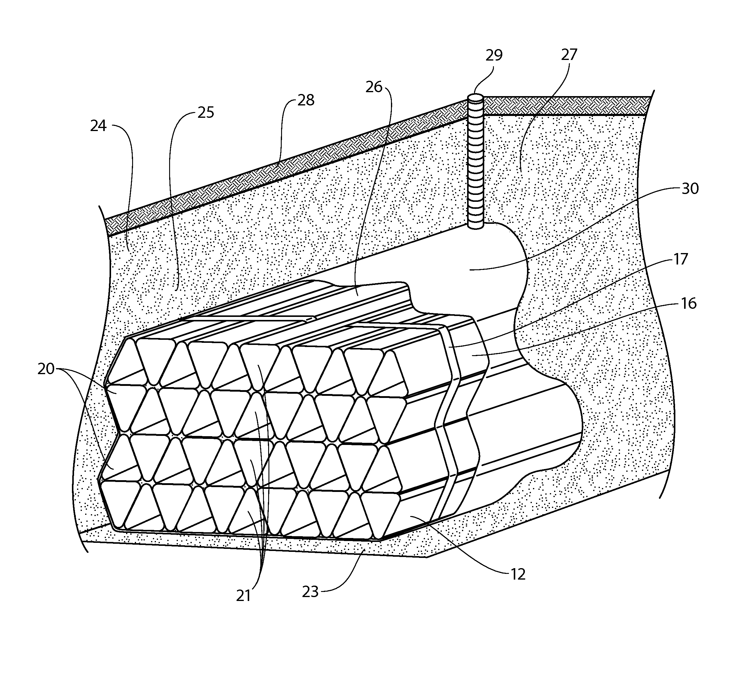
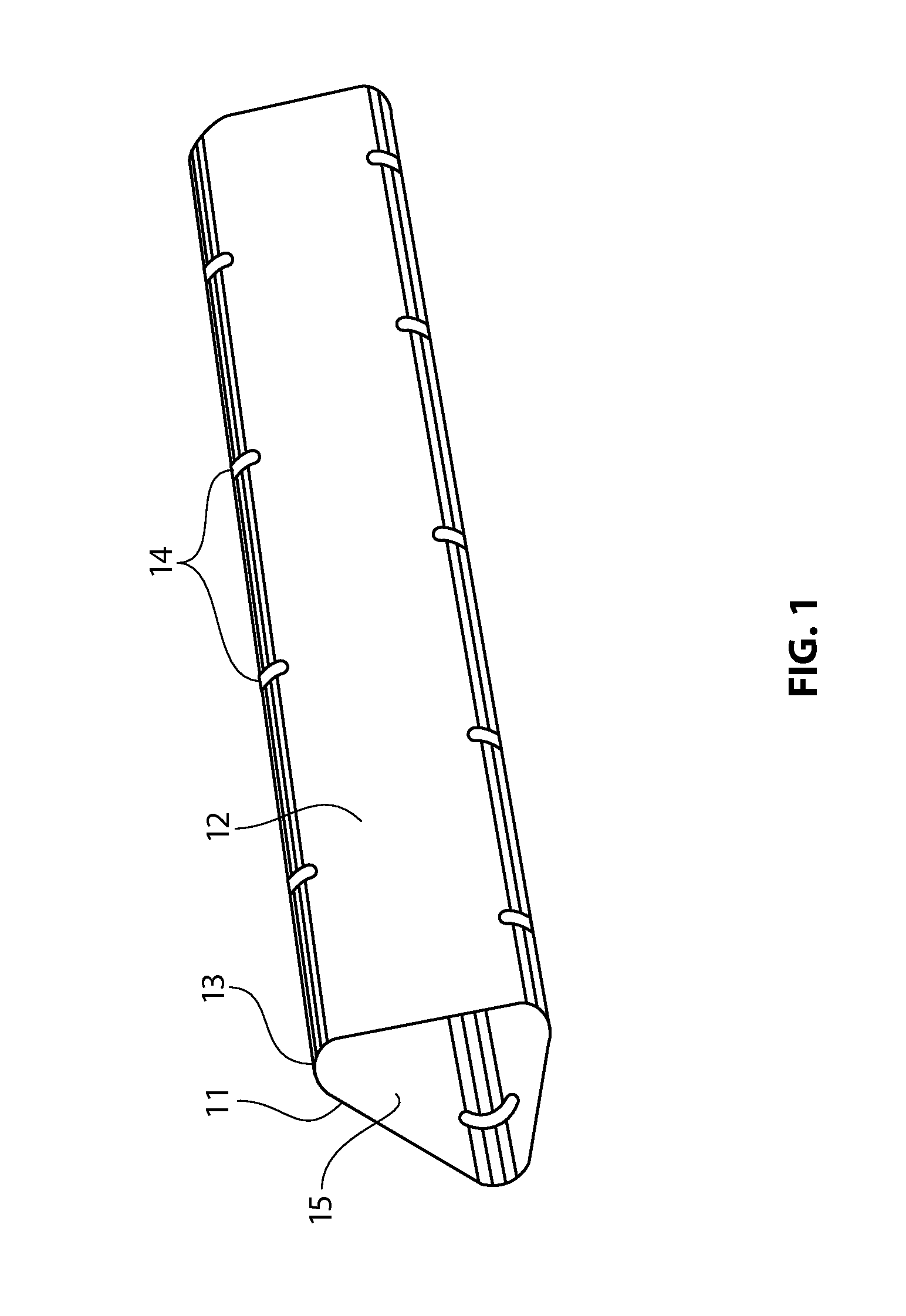
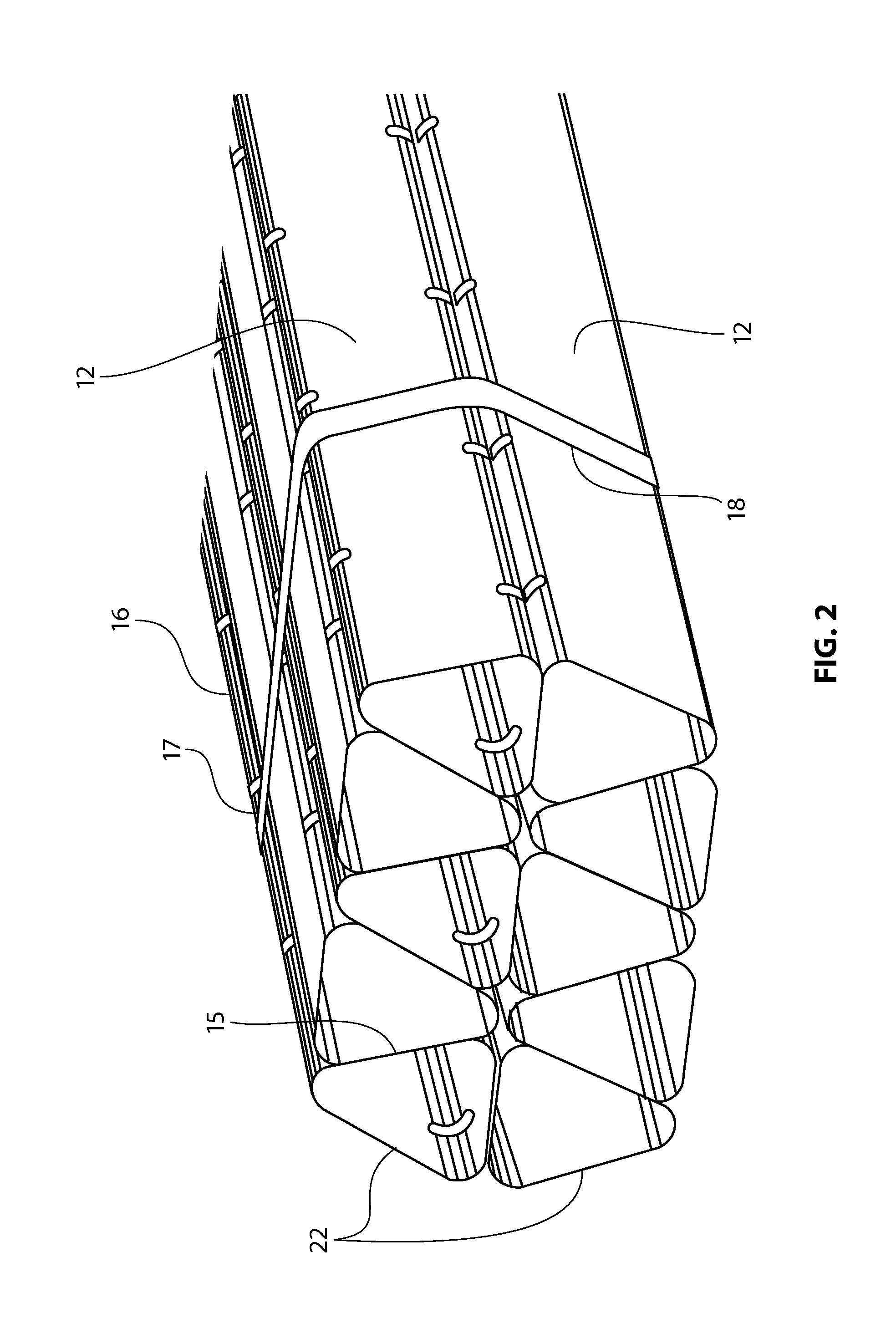
Apparatus and method of supporting underground fluid and water storage and retention systems
a technology of underground fluid and storage and storage, applied in the direction of service pipe systems, sewage draining, water cleaning, etc., can solve the problems of retaining a substantial quantity of water in the tank or cistern, affecting the quality of the water stored above, and affecting the site, so as to achieve faster installation, less heavy equipment required, and low total installed cost
- Summary
- Abstract
- Description
- Claims
- Application Information
AI Technical Summary
Benefits of technology
Problems solved by technology
Method used
Image

Examples
Embodiment Construction
[0035]Described herein are techniques for the underground storage of water. In the following description, for purposes of explanation, numerous examples and specific details are set forth in order to provide a thorough understanding of the present invention. It will be evident, however, to one skilled in the art that the present invention as defined by the claims may include some or all of the features in these examples alone or in combination with other features described below, and may further include modifications and equivalents of the features and concepts described herein.
[0036]In this document, various methods, processes and procedures are detailed. Although particular steps may be described in a certain sequence, such sequence is mainly for convenience and clarity. A particular step may be repeated more than once, may occur before or after other steps (even if those steps are otherwise described in another sequence), and may occur in parallel with other steps. A second step ...
PUM
 Abstract
Description
Claims
Application Information
 - R&D
- Intellectual Property
- Life Sciences
- Materials
- Tech Scout
- Unparalleled Data Quality
- Higher Quality Content
- 60% Fewer Hallucinations
Browse by: Latest US Patents, China's latest patents, Technical Efficacy Thesaurus, Application Domain, Technology Topic, Popular Technical Reports.
© 2025 PatSnap. All rights reserved.Legal|Privacy policy|Modern Slavery Act Transparency Statement|Sitemap|About US| Contact US: help@patsnap.com