Closed band for percutaneous annuloplasty

a technology of annuloplasty and closed band, applied in the field of valve repair, can solve the problems of reducing cardiac output, reducing total stroke volume, and ultimate weakening of the left ventricl

Active Publication Date: 2015-01-06
VALTECH CARDIO LTD
View PDF227 Cites 122 Cited by
  • Summary
  • Abstract
  • Description
  • Claims
  • Application Information

AI Technical Summary

Benefits of technology

[0004]In some applications of the present invention, the contracting assembly includes one or more longitudinal contracting members coupled to the contracting mechanism. The implantable structure is placed completely around an annulus of an atrioventricular valve of a subject, such that none of the one or more longitudinal contracting members is positioned along an anterior portion of the annulus between fibrous trigones of the valve. The implantable structure is fastened to the annulus. The contracting assembly is then actuated to contract a longitudinal portion of the sleeve not positioned along the anterior portion of the annulus. Tightening of the implantable structure therefore tightens at least a portion of the posterior portion of the annulus, while preserving the length of the anterior portion of the annulus. (The anterior portion of the annulus should generally not be contracted because its tissue is part of the skeleton of the heart). However, the portion of the sleeve deployed along the anterior portion of the annulus prevents dilation of the anterior annulus, because the sleeve is anchored at both ends of the anterior annulus, and the sleeve typically comprises a longitudinally non-extensible material. This deployment configuration may help prevent long-term resizing of annulus, especially the anterior annulus, which sometimes occurs after implantation of partial annuloplasty rings, such as C-bands.
[0007]For some applications, the sleeve has first and second sleeve ends, and first and second portions that longitudinally extend from the first and the second sleeve ends, respectively. The sleeve is arranged in a closed loop, such that the first and second portions of the sleeve together define a longitudinally overlapping portion of the sleeve positioned at least partially along the anterior portion of the annulus, and none of the one or more longitudinal contracting members is positioned along the overlapping portion of the sleeve. For some applications, at least one of the tissue anchors penetrates both the first and second portions of the sleeve at the overlapping portion. Such a mutual anchor helps ensure that the first and second portions remain tightly coupled together and to the tissue, so that the sleeve retains its closed loop shape. Alternatively, for some applications, the sleeve is shaped so as to define an integrally closed loop having no sleeve ends.
[0011]In some applications of the present invention, the implantable structure further comprises an elongated linking member, which is positioned along an anterior portion of the annulus, so as to join the ends of the implantable structure in a complete loop. Over time after implantation, the linking member becomes fixed to the anterior portion of the annulus, thereby helping prevent long-term dilation of the anterior annulus. Typically, at least a portion of the linking member is disposed within and covered by the sleeve, into and / or over which fibrous tissue grows over time, helping anchor the linking member to tissue of the anterior annulus. Typically, in this configuration of the implantable structure, none of the anchors is coupled to the anterior portion of the annulus.
[0013]For some applications, the linking member is configured as a spring, which is typically curved, so as to be elastic in a radial direction, i.e., to be compressible like a bow or deflected beam. In these applications, the linking member is oriented such that it is pressed by elasticity against the anterior portion of the mitral annulus, i.e., the outer wall of the aorta, thereby holding the sleeve covering the linking member against the aortic wall. For some applications, at least two of the tissue anchors are coupled to the sleeve at respective, different longitudinal sites alongside the linking member, within 6 cm of the first end of the linking member. These tissue anchors may help set the proper direction of curvature of the linking member, for applications in which the linking member is curved.

Problems solved by technology

Mitral regurgitation of blood from the left ventricle into the left atrium results in increased total stroke volume and decreased cardiac output, and ultimate weakening of the left ventricle secondary to a volume overload and a pressure overload of the left atrium.
Such anchors may be inappropriate for coupling to the anterior portion.

Method used


Image

  • Closed band for percutaneous annuloplasty
  • Closed band for percutaneous annuloplasty
  • Closed band for percutaneous annuloplasty

Examples


Embodiment Construction

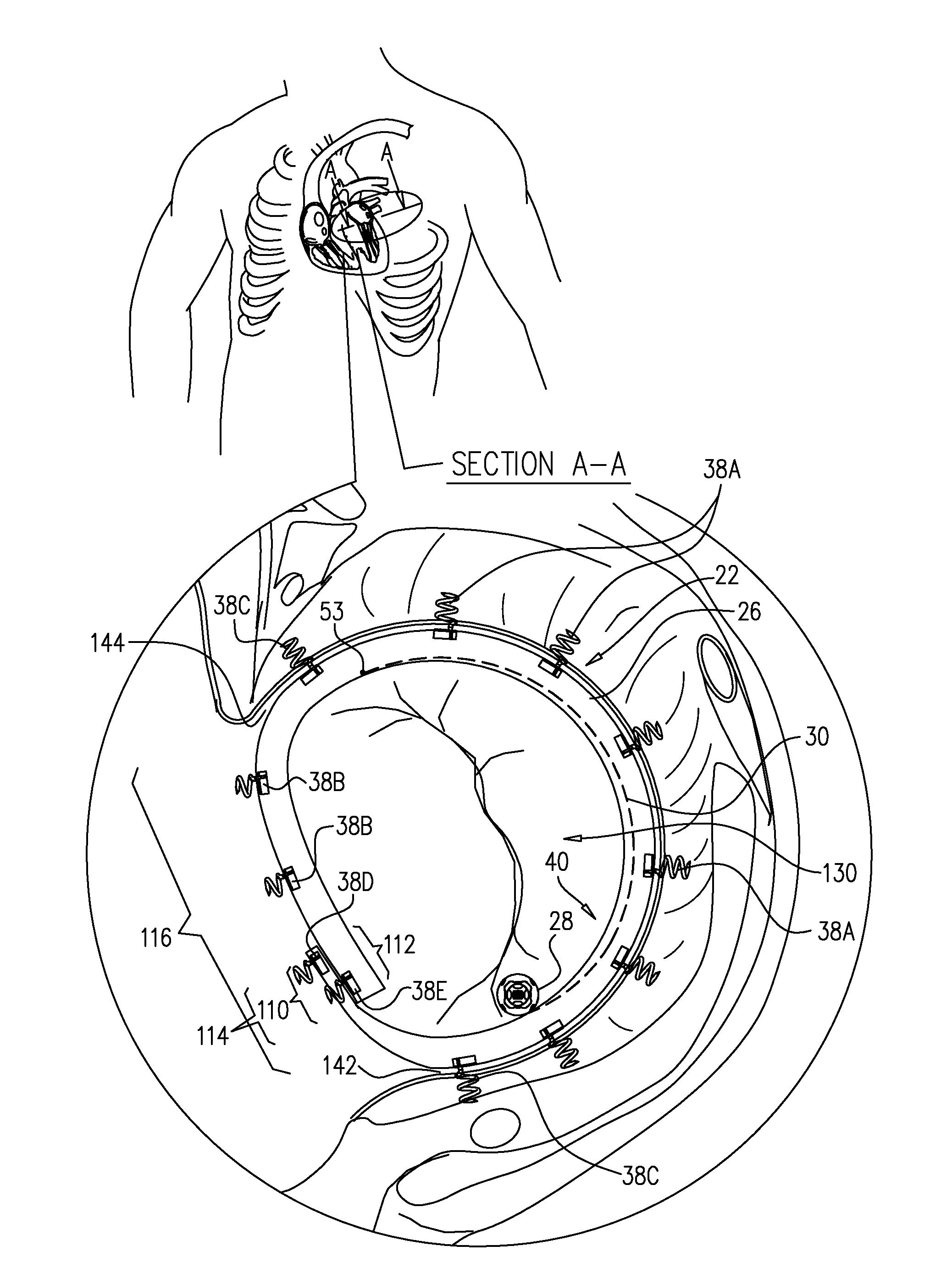
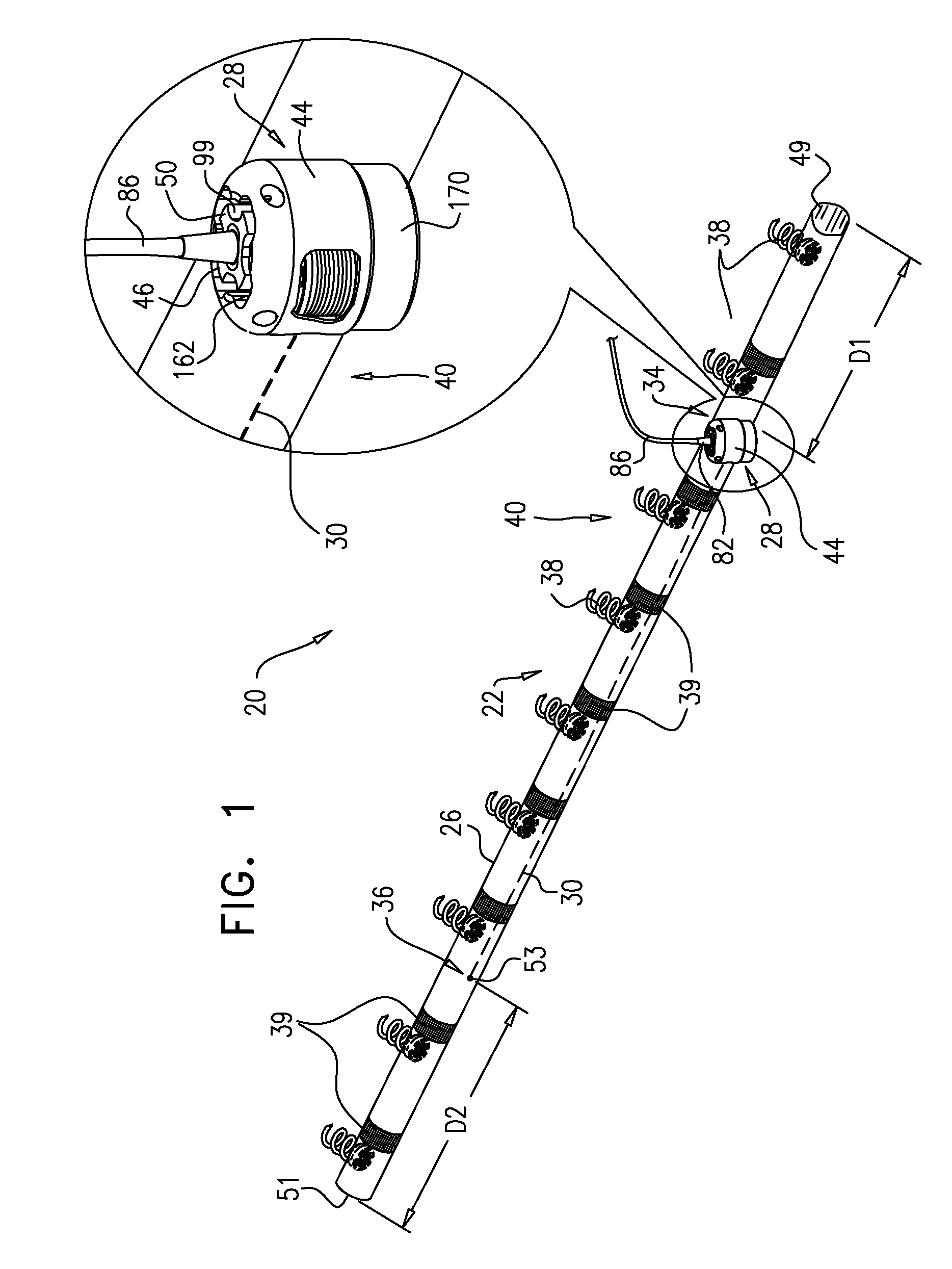
[0208]FIG. 1 is a schematic illustration of a system 20 for repairing a dilated atrioventricular valve, such as a mitral valve or a tricuspid valve, in accordance with an application of the present invention. System 20 comprises an adjustable implantable structure 22, shown in FIG. 1 in a straight, relaxed, non-contracted state, and an anchor deployment manipulator 24 (shown in FIGS. 2G-H). For some applications, implantable structure 22 is configured to be deployed as an annuloplasty ring, while for other applications, implantable structure 22 is configured to be deployed as a base ring to which a prosthetic valve is coupled, such as described hereinbelow with reference to FIG. 15A-B or 16. Implantable structure 22 comprises a flexible sleeve 26. Anchor deployment manipulator 24 is advanced into sleeve 26, as shown in FIGS. 2G-H, and, from within the sleeve, deploys tissue anchors through a wall of the sleeve into cardiac tissue, thereby anchoring the ring around at least a portion...


PUM


Abstract

An implantable structure includes a flexible sleeve, having first and second sleeve ends, and a contracting assembly, which is configured to longitudinally contract the sleeve, and includes a contracting mechanism, which is disposed longitudinally at a first site of the sleeve, and a longitudinal contracting member, having (a) a first member end, (b) a second member end, which is coupled to the sleeve longitudinally at a second site longitudinally between the first site and the second sleeve end, exclusive, and (c) a first member end portion, which is coupled to the contracting mechanism. The sleeve is arranged in a closed loop, such that first and second portions of the sleeve together define a longitudinally overlapping portion of the sleeve. The implantable structure is configured such that the contracting assembly longitudinally applies a longitudinal contracting force only between the first and the second sites, and not along the overlapping portion.

Description

FIELD OF THE APPLICATION[0001]Some applications of the present invention relate in general to valve repair, and more specifically to repair of an atrioventricular valve of a patient.BACKGROUND OF THE APPLICATION[0002]Dilation of the annulus of the mitral valve prevents the valve leaflets from fully coapting when the valve is closed. Mitral regurgitation of blood from the left ventricle into the left atrium results in increased total stroke volume and decreased cardiac output, and ultimate weakening of the left ventricle secondary to a volume overload and a pressure overload of the left atrium. Dilation of the annulus is sometimes treated by annuloplasty, in which a partial or full ring is implanted around the annulus to cause the leaflets to coapt when the valve is closed.SUMMARY[0003]In some applications of the present invention, an implantable structure is provided that comprises a flexible sleeve having first and second sleeve ends, a contracting assembly, and a plurality of tiss...

Claims


Application Information

Patent Timeline
Patent Type & Authority Patents(United States)
IPC IPC(8): A61F2/24
CPCA61F2/2445A61F2/2466
Inventor GROSS, AMIRSHEPS, TALHAMMER, TALREICH, TAL
Owner VALTECH CARDIO LTD
Why Eureka
Try Eureka