Method for identifying abnormal spectral profiles measured by a chromatic confocal range sensor

a confocal range and sensor technology, applied in the field of precision measurement instruments, can solve the problems of unpredictability of two spectral peak detections, and inability to detect more than one spectral peak, etc., and achieve the effect of reliable and robustness

Active Publication Date: 2015-01-06
MITUTOYO CORP
View PDF27 Cites 4 Cited by
  • Summary
  • Abstract
  • Description
  • Claims
  • Application Information

AI Technical Summary

Benefits of technology

[0014]In some applications of a chromatic range sensor, it has been known to eliminate outlier measurements of a surface profile (e.g., a screw thread profile) based on geometric outlier considerations. It will be appreciated that the systems and methods disclosed herein may provide a more robust and reliable method for distinguishing erroneous CRS measurements than such ad hoc geometric methods, providing direct identification of unreliable measurements and / or measurement locations on a workpiece for both unskilled and skilled users.

Problems solved by technology

All of the other wavelengths are poorly focused on the aperture, and so will not couple much power into the fiber.
In various chromatic range sensor systems, there is nothing to prevent the detection of more than one spectral peak based on the light reflected from an intended measurement location.
However, in other cases, two spectral peaks may occur unpredictably (e.g., due to an unexpected secondary reflection that passes back through a primary or intended measurement location).
This may lead to an unexpected and / or erroneous measurement result (e.g., measurement errors that are a significant portion of the measurement range, for example).

Method used


Image

  • Method for identifying abnormal spectral profiles measured by a chromatic confocal range sensor
  • Method for identifying abnormal spectral profiles measured by a chromatic confocal range sensor
  • Method for identifying abnormal spectral profiles measured by a chromatic confocal range sensor

Examples


Embodiment Construction

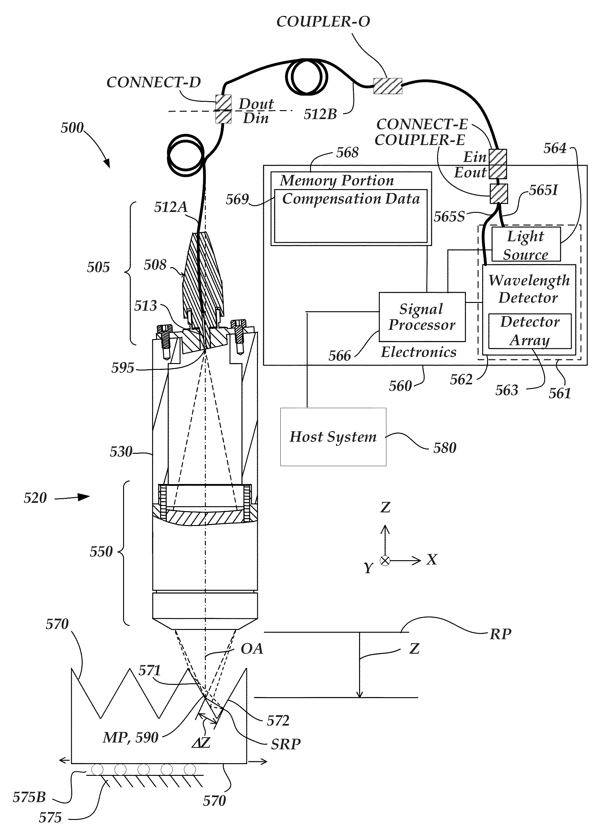
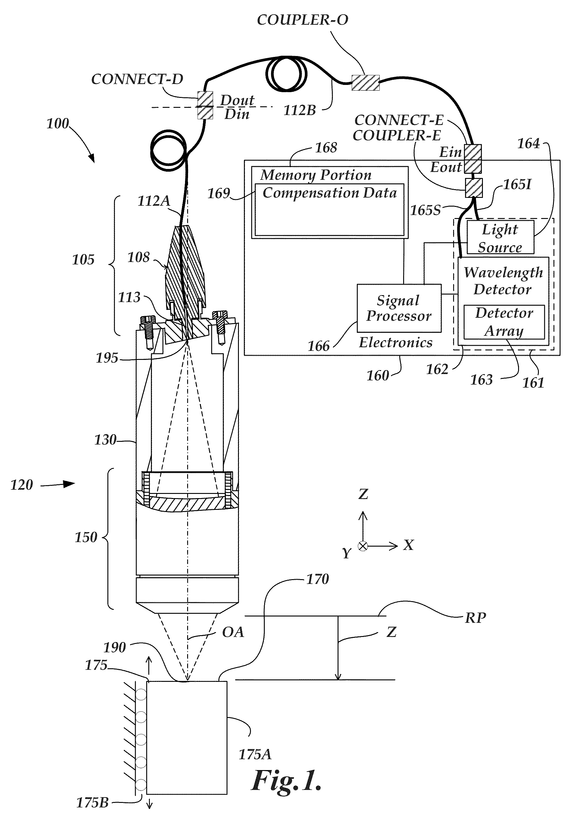
[0024]FIG. 1 is a block diagram of one exemplary embodiment of a chromatic range sensor (CRS) system 100. As shown in FIG. 1, the CRS system 100 includes an optical element 120 and an electronics portion 160. In the embodiment shown in FIG. 1, the electronics portion 160 includes a signal processor 166, a memory portion 168 and a source+detector subsystem 161 comprising a wavelength detector 162, and a broadband light source 164 (also referred to as a white light source, in some embodiments). It should be appreciated that the CRS system 100 shown in FIG. 1 is a chromatic point sensor system which measures a single measurement point at a time. The optical element 120 shown in FIG. 1 is an optical pen. However, in various embodiments alternative types of chromatic range systems, such as a chromatic line sensor, may be configured to operate according to the systems and methods disclosed herein. In various embodiments, the wavelength detector 162 includes a detector array 163 of a spect...


PUM


Abstract

A method for operating a chromatic range sensor (CRS) system to identify abnormal spectral profiles arising from light reflected from more than one portion of a workpiece surface is provided. The method comprises: providing a CRS system comprising: an optical element, a light source, and CRS electronics comprising a CRS wavelength detector; operating the CRS system to receive an output spectral profile from a measurement point on a workpiece surface and provide corresponding output spectral profile data; analyzing the output spectral profile data to provide a peak region asymmetry characterization; and providing a corresponding abnormality indicator if the peak region asymmetry characterization indicates that the peak region is abnormally asymmetric.

Description

FIELD OF THE INVENTION[0001]The invention relates generally to precision measurement instruments, and more particularly, to chromatic range sensors and similar optical distance determining devices and their use.BACKGROUND OF THE INVENTION[0002]It is known to use chromatic confocal techniques in optical height or distance or range sensors. As described in U.S. Pat. No. 7,876,456 (the '456 patent), which is hereby incorporated herein by reference in its entirety, an optical element having axial chromatic aberration, also referred to as axial or longitudinal chromatic dispersion, may be used to focus a broadband light source such that the axial distance to the focus varies with the wavelength. Thus, only one wavelength will be precisely focused on a surface, and the surface height or distance relative to the focusing element determines which wavelength is best focused. Upon reflection from the surface, the light is refocused onto a small detector aperture, such as a pinhole or the end ...

Claims


Application Information

Patent Timeline
Patent Type & Authority Patents(United States)
IPC IPC(8): G01J3/00G01C5/00G01C3/08G01B11/30G01B11/24G01C3/00
CPCG01B11/303G01B11/0608G01B2210/50
Inventor PATZWALD, ANDREW MICHAEL
Owner MITUTOYO CORP
Why Eureka
Try Eureka