
DC to DC converting circuit

a converting circuit and converting circuit technology, applied in the direction of electric variable regulation, process and machine control, instruments, etc., can solve the problems of wasting electric power, narrow operation range in design and manufacture, and low power conversion efficiency of traditional dc to dc converters, so as to avoid surge voltage and improve voltage conversion efficiency.

Active Publication Date: 2015-01-06
NAT CHUNG SHAN INST SCI & TECH
View PDF10 Cites 0 Cited by
  • Summary
  • Abstract
  • Description
  • Claims
  • Application Information

AI Technical Summary

Benefits of technology

The patent is about a circuit that helps reduce surge voltage and improve the efficiency of voltage conversion. This can be useful in various applications where DC to DC conversion is necessary.

Problems solved by technology

Traditional DC to DC converter is faced with limitation of low power converting efficiency and narrow operation range in design and manufacture.
The way aforementioned wastes electric power because it can not optimize the circuit design and select a normal input voltage range of resonating network parameters adaptively.
The primary disadvantages of which are that a larger frequency range is required for tuning output of a large load and the output can not be well tuned in zero load condition.
Besides, the full-bridge converter causes the switch generating a surge voltage between drain electrode and source electrode due to inductance loss of the switching moment of the switch and imbalance of the switch characteristics.
The surge voltage decreases the circuit stability and reliability.

Method used


Image

  • DC to DC converting circuit
  • DC to DC converting circuit
  • DC to DC converting circuit

Examples


Embodiment Construction

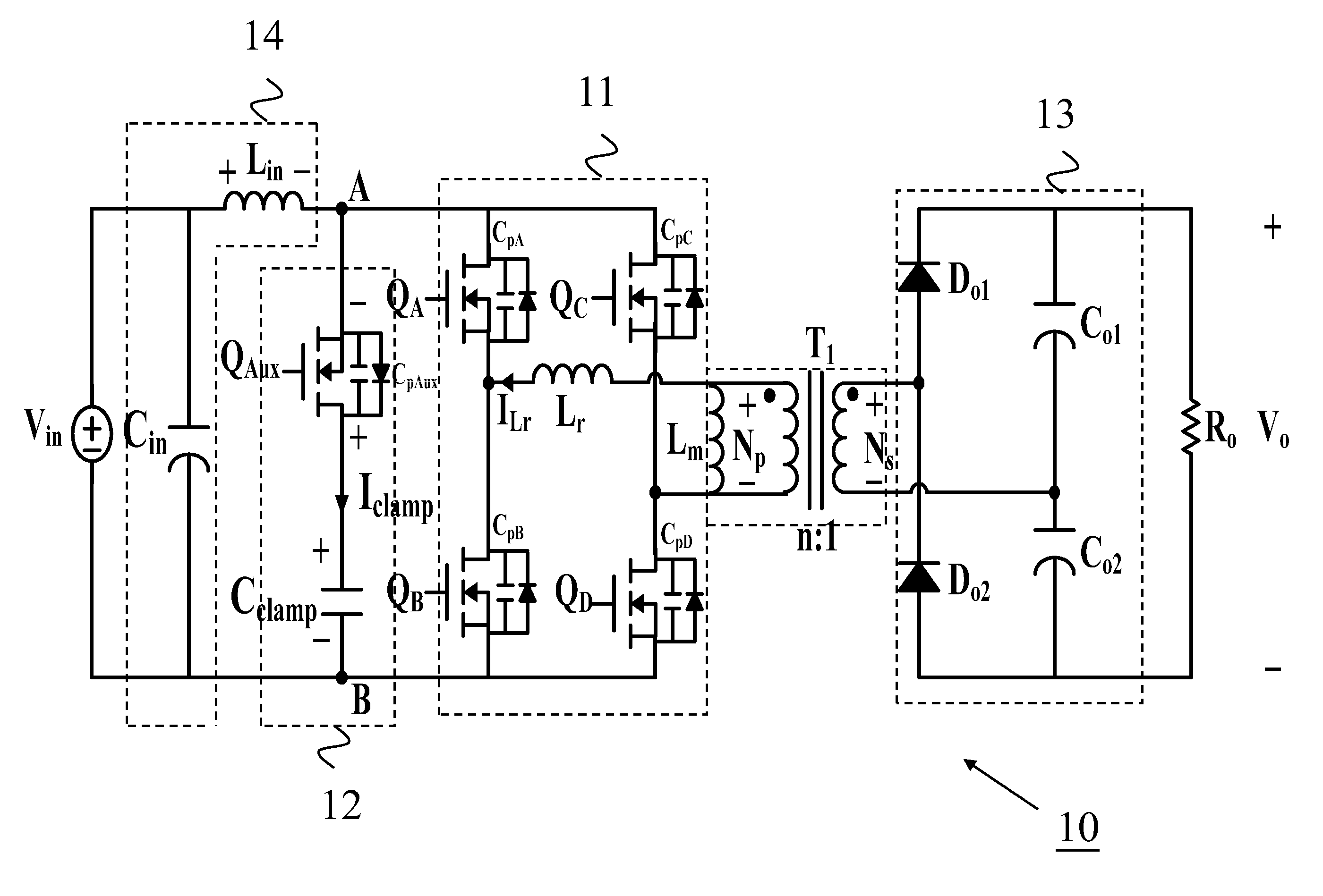
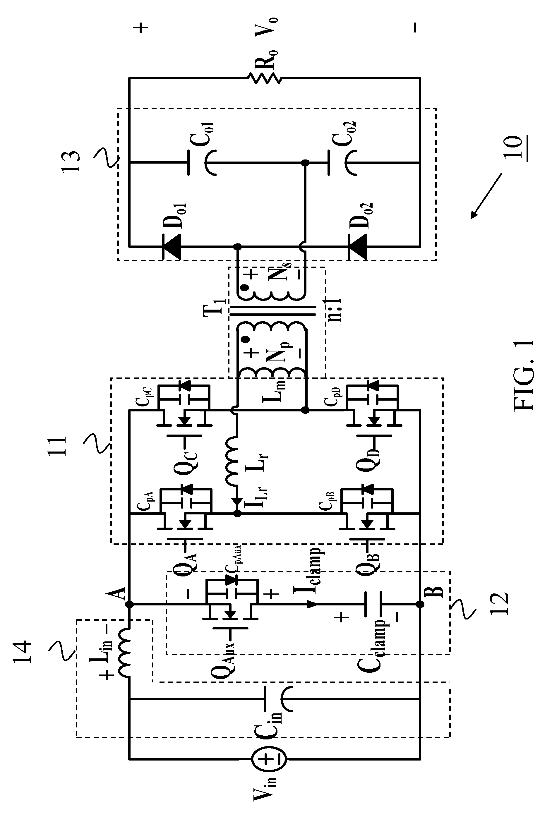
[0012]The technical characteristic of clamping technology is to replace the Snubber diode by an active switch for operating in high frequency circumstance. Energy generated by surge voltage is fed back to input power source for reducing power loss of the voltage converter. The present invention is practiced by the clamping technology. For clarity of disclosure, and not by way of limitation, the detailed description of the invention is divided into the subsections that follow.

[0013]FIG. 1 is a circuit diagram of the DC to DC converting circuit of the present invention. As shown, the DC to DC converting circuit 10 is substantially composed of a transforming unit T1, a bridge rectifier unit 11, a clamping unit 12 and an output unit 13. The transforming unit T1 has a primary winding and a secondary winding. The bridge rectifier unit 11 is coupled to an input voltage Vin, having a first output terminal and a second output terminal coupled to both side of the primary winding respectively,...


PUM


Abstract

The invention provides a DC to DC converting circuit, comprising: a transforming unit with a primary winding and a secondary winding; a bridge rectifier unit coupled to an input voltage, having a first output terminal and a second output terminal coupled to both side of the primary winding respectively; a first switch coupled between the input voltage and the first output terminal; a second switch coupled between the first output terminal and a ground terminal; a third switch coupled between the input voltage and the second output terminal; and a fourth switch coupled between the second output terminal and the ground terminal; an output unit paralleled to the secondary winding; and a clamping unit coupled to the input voltage and paralleled to the bridge rectifier unit, having an auxiliary switch coupled to the input voltage; and a clamping capacitor coupled between the auxiliary switch and the ground terminal; wherein the auxiliary switch is turned on when operation statuses of the first switch and the fourth switch or the second switch and the third switch are changed.

Description

FIELD OF THE INVENTION[0001]This invention relates to a voltage converting circuit, and more particularly, to a DC to DC converting circuit for avoiding surge voltage and improving voltage converting efficiency.BACKGROUND OF THE INVENTION[0002]Fuel cell is a device without storing ability for converting chemical energy to electric power directly. When the loading is increased, output voltage of fuel cell is then decreased. Thus, a DC to DC converter is necessarily to dispose between the fuel cell and the loading for providing a stable voltage source to the loading and increasing the application fields. Traditional DC to DC converter is faced with limitation of low power converting efficiency and narrow operation range in design and manufacture. For achieving a holding time period in input voltage decreasing circumstance, operation cycle and other operation parameters should be tuned for achieving the requirement of the holding time period in low input voltage condition. On the other...

Claims


Application Information

Patent Timeline
Patent Type & Authority Patents(United States)
IPC IPC(8): H02M3/335H02M1/00H02M3/337
CPCH02M3/33507H02M3/337H02M2001/0058Y02B70/10H02M1/0058H02M3/33573H02M3/01
Inventor JEN, KUO-KUANGLIAO, YU-MINHUANG, CHEN-HOKAO, CHIEN-MINYOU, GWO-HUEI
Owner NAT CHUNG SHAN INST SCI & TECH
Learn More