
Acousto-optic integrated independent wireless gas detector system

A gas detector, integrated technology, applied in the direction of analyzing gas mixtures, instruments, measuring devices, etc., can solve the problems of high surge voltage, easy burnout of contacts, high power consumption of thyristors, etc.

Active Publication Date: 2022-02-01
河南驰诚电气股份有限公司
View PDF6 Cites 0 Cited by
  • Summary
  • Abstract
  • Description
  • Claims
  • Application Information

AI Technical Summary

Problems solved by technology

[0003] The switch circuit of the AC 220V power supply solenoid valve (referred to as solenoid valve) in the gas detector on the market uses a 250VAC mechanical contact relay to control the switch. Since the solenoid valve is an inductive load, when the solenoid valve is switched, the surge voltage of the solenoid valve power supply is relatively high. , Ordinary mechanical relay contacts are easy to burn out and easy to stick. Using RC suppression circuit requires high-voltage and high-power devices. The device is large in size, which can only delay the life of the relay contacts, but cannot completely avoid contact sticking or burning out.
In the prior art, the thyristor is a switch control element, which can not only be used as a switch element alone, but also can be combined with a mechanical contact relay to realize a composite switch. However, although the above switch can achieve certain effects, its structure It is more complicated, and the power consumption, especially the power consumption of the thyristor, is relatively large (especially at high current), and it is usually a separate combined component for circuit design, and the structure and power consumption are relatively large. Therefore, a design is made. There is a strong demand for integrated, simple, reliable and low-power solenoid valve integrated switches

Method used


Image

  • Acousto-optic integrated independent wireless gas detector system
  • Acousto-optic integrated independent wireless gas detector system
  • Acousto-optic integrated independent wireless gas detector system

Examples


Embodiment Construction

[0014] The implementation mode of the present invention is illustrated by specific specific examples below, and those who are familiar with this technology can easily understand other advantages and effects of the present invention from the contents disclosed in this description. Obviously, the described embodiments are a part of the present invention. , but not all examples. Based on the embodiments of the present invention, all other embodiments obtained by persons of ordinary skill in the art without making creative efforts belong to the protection scope of the present invention.

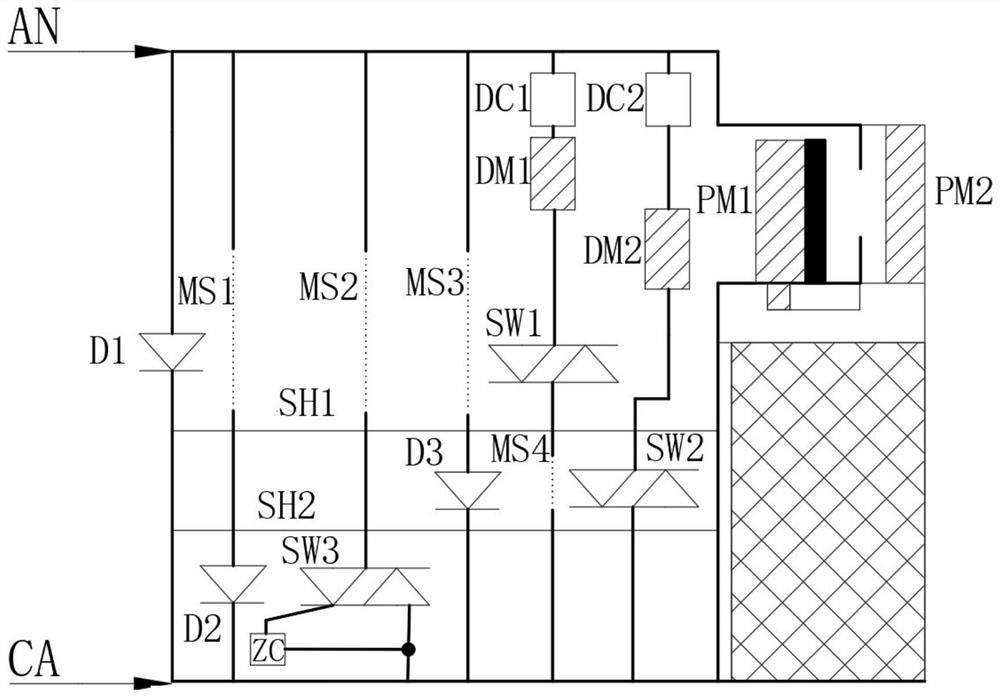
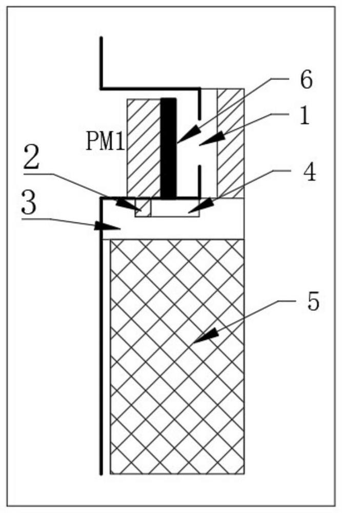
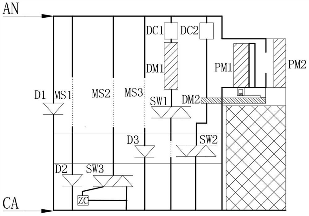
[0015] Please refer to Figure 1-2As shown, an integrated control switch for controlling a solenoid valve linked with a gas detector, including a first light-emitting diode D1, a second light-emitting diode D2, a third light-emitting diode D3, a first switch SW1, and a second switch SW2 , the third switch SW3, the zero-crossing detection circuit ZC, the first rectification filter circuit DC1, th...


PUM


Abstract

The invention relates to an acousto-optic integrated independent wireless gas detector system and an integrated control switch for controlling an electromagnetic valve linked with a gas detector. The system mainly comprises a first light-emitting diode D1, a second light-emitting diode D2, a third light-emitting diode D3, a first switch SW1, a second switch SW2, a third switch SW3, a zero-cross detection circuit ZC, a first rectification filter circuit DC1, a second rectification filter circuit DC2, a first driving part DM1, a second driving part DM2, a first shielding part SH1, a second shielding part SH2, a first permanent magnet PM1, a second permanent magnet PM2, a first grid plate MS1. a second grid plate MS2, a third grid plate MS3, a fourth grid plate MS4, a notch part, a sliding block, a square block, a groove and a supporting part.

Description

technical field [0001] The invention relates to an acousto-optic integrated stand-alone wireless gas detector system, and more particularly relates to an integrated control switch for controlling a solenoid valve linked with the gas detector. Background technique [0002] The wireless gas detector is connected to the control host through a wireless signal, the detector signal is transmitted to the control host, and the control host then feeds back the signal to the solenoid valve, and the linkage solenoid valve cuts off the gas source. [0003] The switch circuit of the AC 220V power supply solenoid valve (referred to as solenoid valve) in the gas detector on the market uses a 250VAC mechanical contact relay to control the switch. Since the solenoid valve is an inductive load, when the solenoid valve is switched, the surge voltage of the solenoid valve power supply is relatively high. , Ordinary mechanical relay contacts are easy to burn out and easy to stick. Using RC suppr...

Claims


Application Information

Patent Timeline
IPC IPC(8): G01N33/00H01H3/22
CPCG01N33/0004H01H3/22
Inventor 石保敬吴志峰张静王长荀
Owner 河南驰诚电气股份有限公司
Learn More