Multi-function vibration actuator

a multi-functional, actuator technology, applied in the direction of mechanical vibration separation, transducer details, electrical transducers, etc., can solve the problems of insufficient use of vibration force working to the inside of the suspension in a torsion direction, inability to obtain sufficient somesthetic vibration, and inability to reduce the arrangement space of the suspension. , to achieve the effect of reducing the attachment area of the suspension supporting section, increasing the length of each arm, and stable vibration characteristics

Inactive Publication Date: 2015-01-06
NAMIKI PRECISION JEWEL CO LTD
View PDF3 Cites 0 Cited by
  • Summary
  • Abstract
  • Description
  • Claims
  • Application Information

AI Technical Summary

Benefits of technology

[0009]The present invention is contrived to solve the above-described problems. An advantage of the present invention is to provide a multi-function vibration actuator which is simply configured into a rectangular shape and obtains stable vibration characteristics by a simple structure.
[0010]In order to solve the above-described problems, the invention described herein is characterized in that a magnetic circuit section is supported in a housing a frame-shaped suspension.
[0011]In more detail, the multi-function vibration actuator of the present invention does not use a suspension structure in which the magnetic circuit section is elastically supported by each arm extending independently, but uses a structure in which the magnetic circuit section is supported on the inner wall of the housing at frame-shaped sections.
[0012]Accordingly, it is possible to reduce the attachment area of suspension supporting sections and to increase the length of each arm occupied in the suspension compared with a conventional suspension for supporting the magnetic circuit section by each arm. Therefore, a force which operates to the inside of the suspension upon driving and a force in a bending direction along the arm can be received in a wider range of the suspension.
[0013]By using the frame shape, since stress applied to the above-described suspension is received in a range wider than that of the conventional technique, a structure which is tough against deformation is obtained and the suspension is hard to be deformed when impact is received upon dropping. In the conventional technique, it is possible to obtain stable vibration characteristics compared with the above-described structure in which the magnetic circuit section is supported by the arm.
[0014]The invention is further characterized in that the suspension supporting sections are symmetrically arranged when the frame-shaped suspension is supported. Therefore, it is possible to make a force applied to the suspension uniform.

Problems solved by technology

Accordingly, it is difficult to reduce the arrangement space of the suspension.
Therefore, the vibration force which works to the inside of the suspension in a torsion direction may not be sufficiently used.
In addition, if the mounting space on the substrate is small, in the multi-function vibration actuator described in Patent Document 1, since the magnetic circuit is small, sufficient somesthetic vibration may not be obtained.

Method used


Image

  • Multi-function vibration actuator
  • Multi-function vibration actuator
  • Multi-function vibration actuator

Examples


Embodiment Construction

[0030]Hereinafter, embodiments of the present invention will be described with reference to FIGS. 1 to 10.

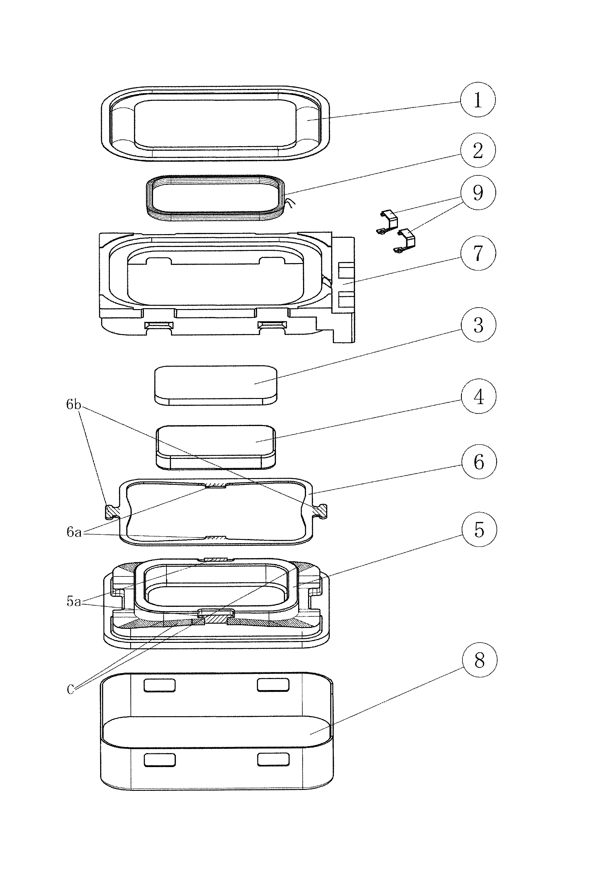
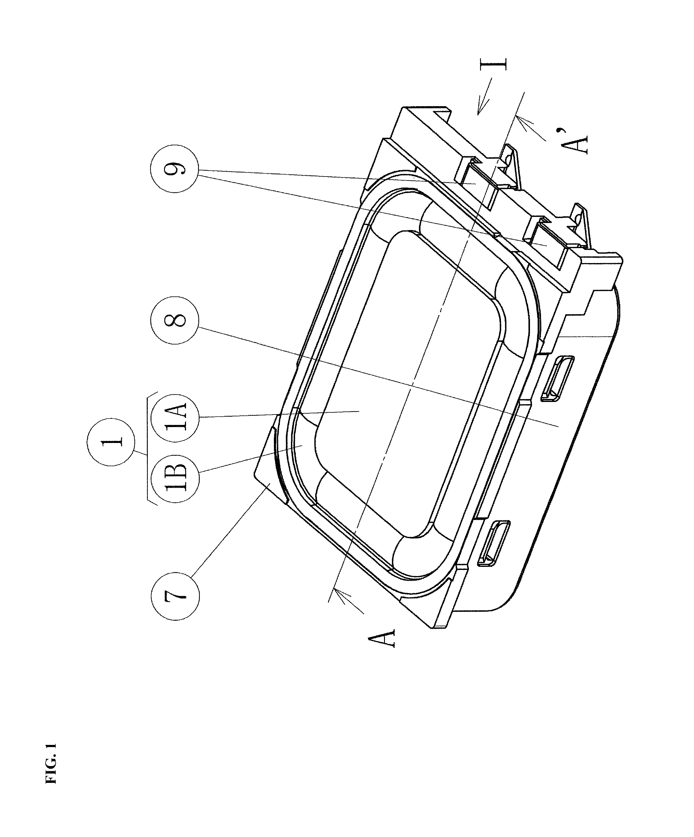
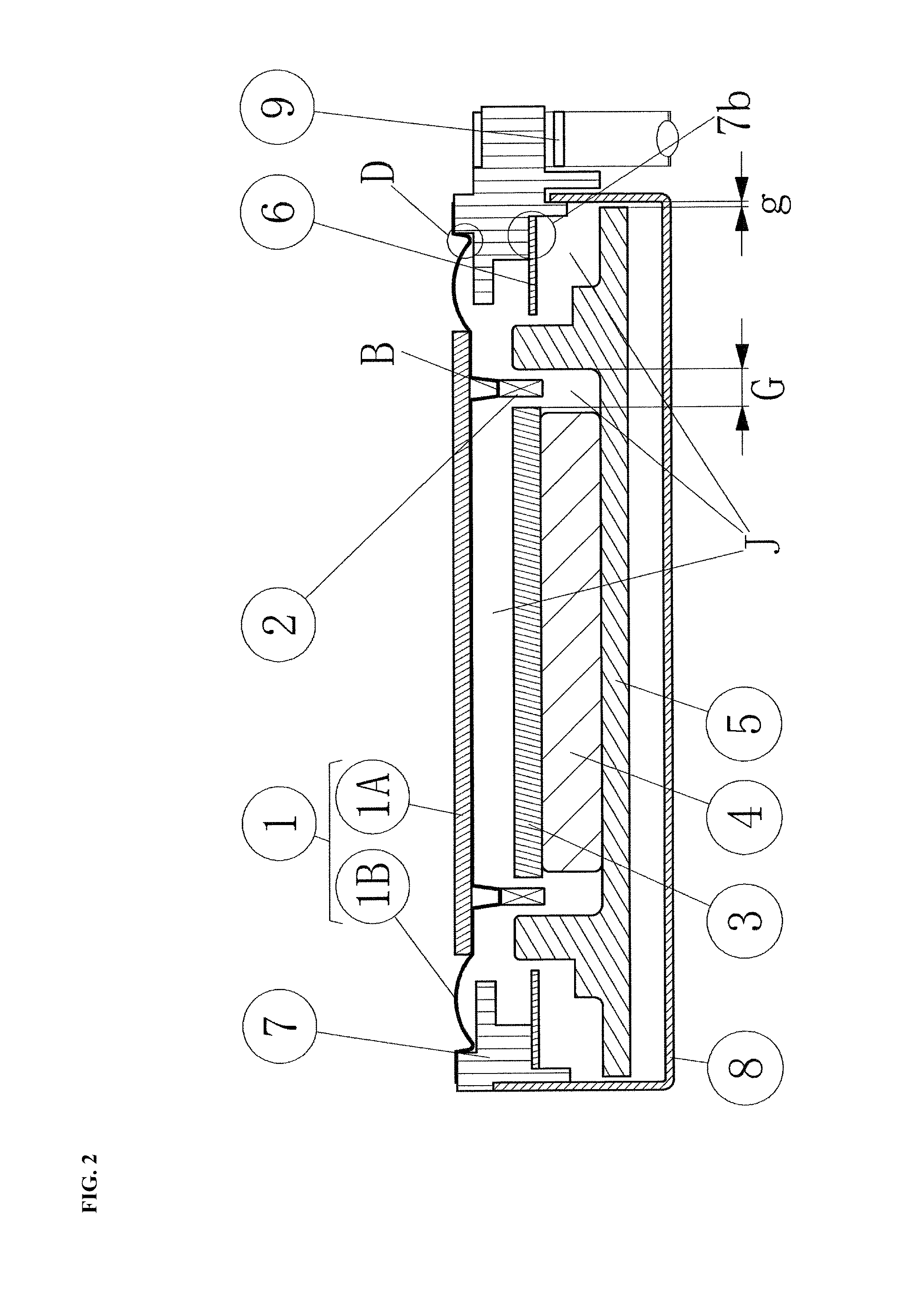
[0031]FIGS. 1 and 2 are a perspective view and a side cross-sectional view of a multi-function vibration actuator used in the present embodiment, respectively. FIG. 2 is a side cross-sectional view taken along line A-A′ of the multi-function vibration actuator shown in FIG. 1.

[0032]Hereinafter, the driving structure of the multi-function vibration actuator according to the present embodiment will be described with reference to FIGS. 1 and 2. As can be seen from FIG. 2, in the multi-function vibration actuator according to the present embodiment, an acoustic reproduction section is configured by attaching a voice coil 2 wound on a diaphragm 1 including a diaphragm central section 1A and a diaphragm base section 1B in an oscillation vibration of the diaphragm 1.

[0033]In addition, a magnetic circuit section is configured by fixing a pole piece 3, which is formed of the same magneti...


PUM


Abstract

A multifunction oscillatory actuator which performs acoustic reproduction by an acoustic reproduction section includes a diaphragm having a voice coil attached thereto and performs the occurrence of somesthetic oscillation by a magnetic circuit section having a magnet attached thereto, and in which the acoustic reproduction section and the magnetic circuit section are attached to a housing having a cylindrical shape, such that the magnetic circuit section is supported on an inner wall of the housing by a frame-shaped suspension.

Description

TECHNICAL FIELD[0001]The present invention relates to a multi-function vibration actuator capable of realizing both acoustic reproduction and the occurrence of somesthetic vibration by switching an input frequency to a voice coil.BACKGROUND ART[0002]Currently, a mobile communication apparatus such as a mobile telephone mainly includes a function of informing call incoming without using a ringing tone by the occurrence of somesthetic vibration as well as a function of informing call incoming using a ringing tone, and multi-function vibration actuators for applying these functions by a single device are used in a part of the models.[0003]Among the above-described multi-function vibration actuators, as one of general structures, Japanese Patent No. 2929579 (hereinafter, referred to as Patent Document 1) is filed and registered, in which the shape of a suspension for supporting a magnetic circuit section having a magnet is partially changed so as to increase the linearity of the suspens...

Claims


Application Information

Patent Timeline
Patent Type & Authority Patents(United States)
IPC IPC(8): H04R25/00B06B1/04H04M19/04H04R9/06
CPCB06B1/045H04M19/04H04R9/06H04M19/047H04R2400/03H04R2499/11B06B1/08H04M1/02H04R9/02
Inventor UEDA, MINORUKUMAGAI, TAKAYUKIHASHIMOTO, YUUICHI
Owner NAMIKI PRECISION JEWEL CO LTD
Why Eureka
Try Eureka