
System and method for energy-saving inductive heating of evaporators and other heat-exchangers

a technology of inductive heating and evaporator, which is applied in the direction of heating types, defrosting, domestic cooling apparatus, etc., can solve the problems of reducing the performance of the evaporator, restricting the airflow through the evaporator, and consuming a great deal of energy, and achieves the effect of increasing the resistan

Active Publication Date: 2015-01-13
TRUSTEES OF DARTMOUTH COLLEGE THE +1
View PDF166 Cites 5 Cited by
  • Summary
  • Abstract
  • Description
  • Claims
  • Application Information

AI Technical Summary

Benefits of technology

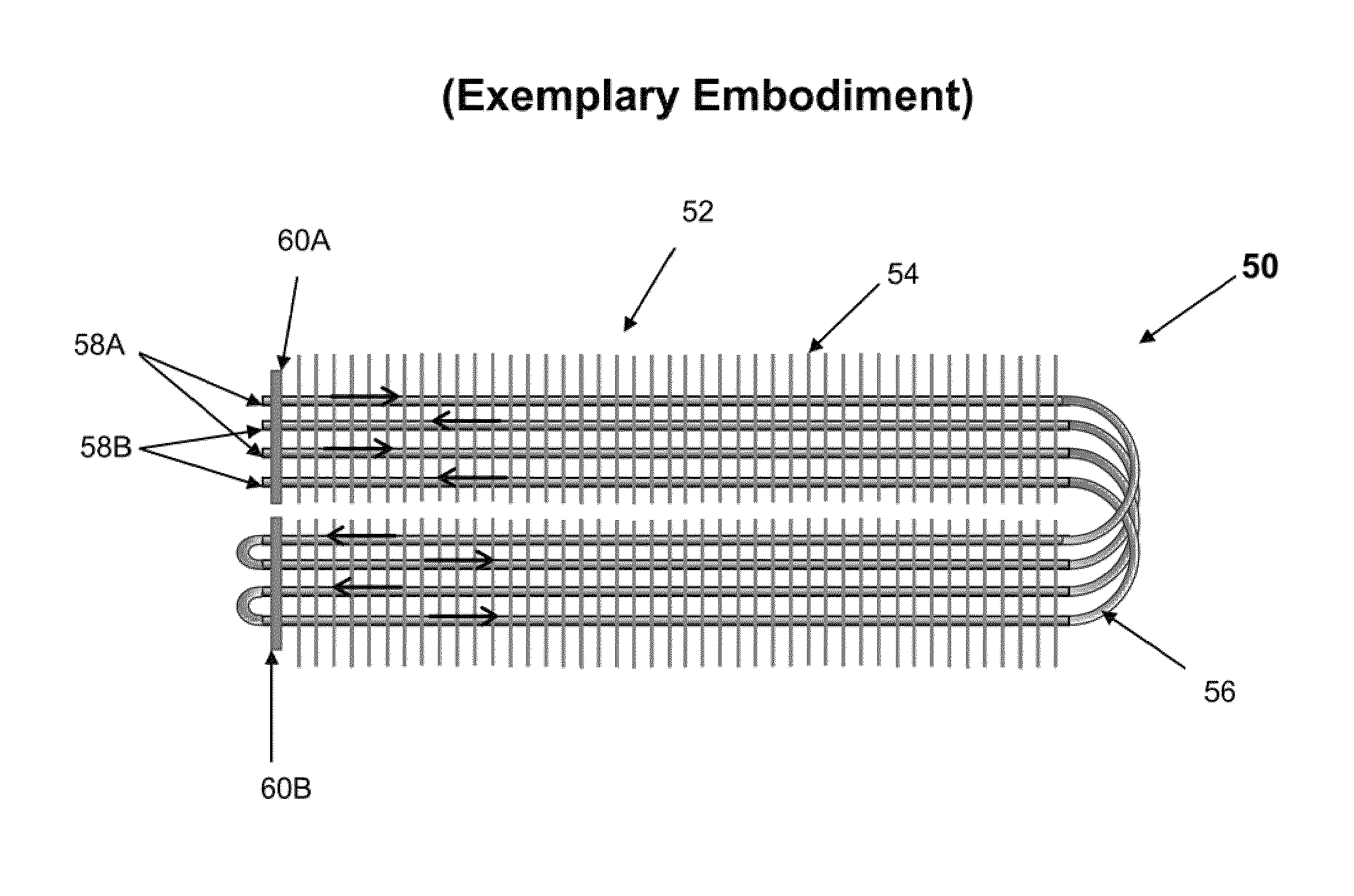
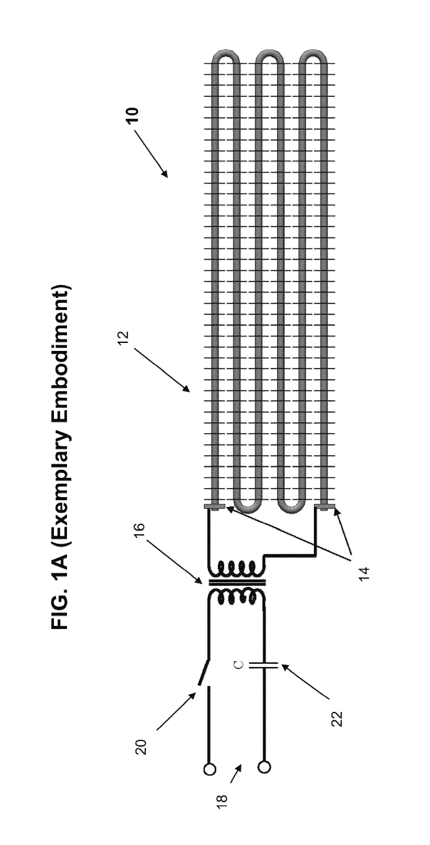
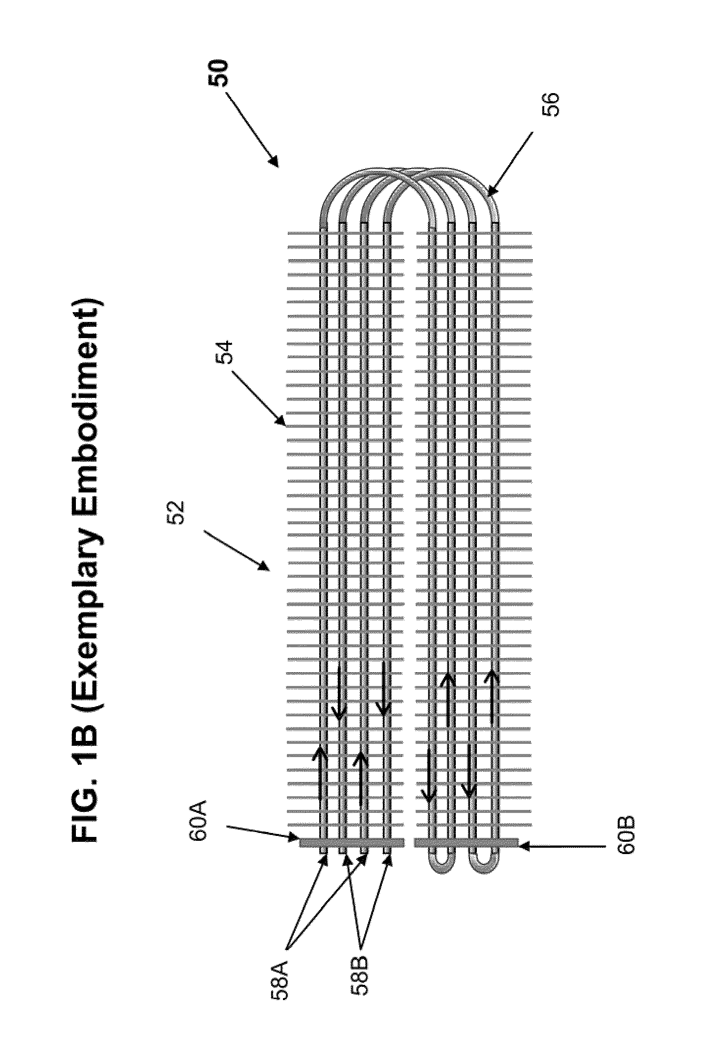
The present invention provides an evaporator / heat exchanger system that is designed for energy-saving and efficient heating using PETD or similar techniques. The system is optimized for this by configuring it to have an increased resistance to the heating process, allowing for the use of such energy-saving techniques. In one embodiment, the system is divided into multiple sections, each containing a tube and a resistor, which further increases the electrical resistance of the system and allows for the use of the energy-saving techniques. Overall, this invention provides a more efficient and energy-saving evaporator / heat exchanger system.

Problems solved by technology

During normal operation, such evaporators accumulate frost on the surfaces of the fins and tubes over time which increasing restricts the airflow through the evaporator and decreases its performance.
However, such defrost cycles are time consuming and thus also consume a great deal of energy and also produce undesirable heat within the space being refrigerated, such as a freezer compartment.
However, a lower fin density also lowers the performance and efficiency of the evaporator.
Unfortunately, while PETD can be readily utilized with specially constructed PETD-enabled evaporators, it is virtually impossible to use PETD with conventional fins-on-tubes evaporators / heat exchanges.
Naturally, it is difficult and quite expensive to provide a power supply for the evaporator that is capable of delivering such a high current.
Even worse, the value of an inductive reactance of conventional evaporators exceed their electrical resistance by more than one order of magnitude.

Method used


Image

  • System and method for energy-saving inductive heating of evaporators and other heat-exchangers
  • System and method for energy-saving inductive heating of evaporators and other heat-exchangers
  • System and method for energy-saving inductive heating of evaporators and other heat-exchangers

Examples


Embodiment Construction

[0028]The present invention provides various advantageous embodiments of a novel fins-on-tubes type evaporator / heat exchanger system that is optimized for energy-saving rapid inductive heating thereof, for example by way of application of Pulse Electro-Thermal Deicing / Defrosting (PETD), or equivalent technique thereto, by configuring an evaporator / heat exchanger to comprise a target resistance value suitable for efficient heating by inductive currents. In accordance with the present invention, for systems employing alternating current electrical power supplies, this target electrical resistance value is preferably of a magnitude that is at least as high as a magnitude of an inductive reactance value of the inventive evaporator / heat-exchanger system.

[0029]The present invention provides a novel, but simple and efficient technique for significantly increasing an evaporators' resistance while keeping its inductance and a refrigerant pressure drop at approximately the same stable value, ...


PUM


Abstract

A novel fins-on-tubes type evaporator / heat exchanger system that is optimized for energy-saving inductive heating thereof by configuring it to increasing its resistance to a value at which the system's reactance at its working frequency is comparable to its electrical resistance. The system includes a set of tubes configured for flow of cooling material therethrough, and also includes a set of fins positioned and disposed perpendicular to, and along, the tubes, in such a way that at least a portion of the fins comprises longitudinal excisions therein.

Description

CROSS REFERENCE TO RELATED APPLICATIONS[0001]The present patent application claims priority from the commonly assigned co-pending U.S. provisional patent application 61 / 263,550 entitled “System and Method for Energy-Saving Inductive Heating of Evaporators and Other Heat-Exchangers”, filed Nov. 23, 2009.FIELD OF THE INVENTION[0002]The present invention relates generally to fins-on-tubes type evaporator and heat exchanger systems, and more particularly to fins-on-tubes type evaporator and heat exchanger systems optimized for energy-saving inductive heating thereof.BACKGROUND[0003]Evaporators and other heat-exchanger systems are in widespread use in an enormous variety of cooling, refrigeration, HVAC, and other applications in virtually every market and market sector ranging from residential, vehicular, commercial, to medical, scientific and industrial.[0004]The most common type of conventional evaporators / heat exchanges is a fins-on-tube configuration (such as shown by way of example ...

Claims


Application Information

Patent Timeline
Patent Type & Authority Patents(United States)
IPC IPC(8): F25D21/08F24D19/00F24H1/10F25B39/02F28D1/047F28D21/00F28F1/32F28F17/00F28G13/00H05B3/02H05B3/42
CPCF24D19/0095F24H1/105F25D21/08F28D1/0477F28F1/32F28F17/00H05B3/023H05B3/42F25B39/02F28D2021/0071F28G13/005H05B3/0009
Inventor PETRENKO, VICTOR F.CHEN, CHENGPETRENKO, FEDOR V.
Owner TRUSTEES OF DARTMOUTH COLLEGE THE
Learn More