
Counterweight-based device for controlling the orientation of fan blades of a turboprop engine

a technology of fan blades and counterweights, which is applied in the direction of gearing, rotors, vessel construction, etc., can solve the problems of difficult adjustment of intermediate parts for guiding in rotation or translation, wear effects, etc., and achieve the effect of low mass and simple implementation

Active Publication Date: 2015-01-13
SN DETUDE & DE CONSTR DE MOTEURS DAVIATION S N E C M A
View PDF7 Cites 10 Cited by
  • Summary
  • Abstract
  • Description
  • Claims
  • Application Information

AI Technical Summary

Benefits of technology

[0005]The present invention has as its principal object to propose a solution for control of the orientation of the fan blades of a turboprop which is simple to implement while still being reliable and having low mass.
[0007]Such a control device exhibits numerous advantages. In particular, it is reliable and lightweight because it has relatively few parts, with simple mechanical connections. In particular, there are no intermediate parts for guiding in rotation or in translation which would have been difficult to adjust and subject to wear effects. Further, the maintenance of such a device is particularly easy because the counterweights that are accommodated on the outside of the rotating ring are easily accessible.

Problems solved by technology

In particular, it is reliable and lightweight because it has relatively few parts, with simple mechanical connections.
In particular, there are no intermediate parts for guiding in rotation or in translation which would have been difficult to adjust and subject to wear effects.

Method used


Image

  • Counterweight-based device for controlling the orientation of fan blades of a turboprop engine
  • Counterweight-based device for controlling the orientation of fan blades of a turboprop engine
  • Counterweight-based device for controlling the orientation of fan blades of a turboprop engine

Examples


Embodiment Construction

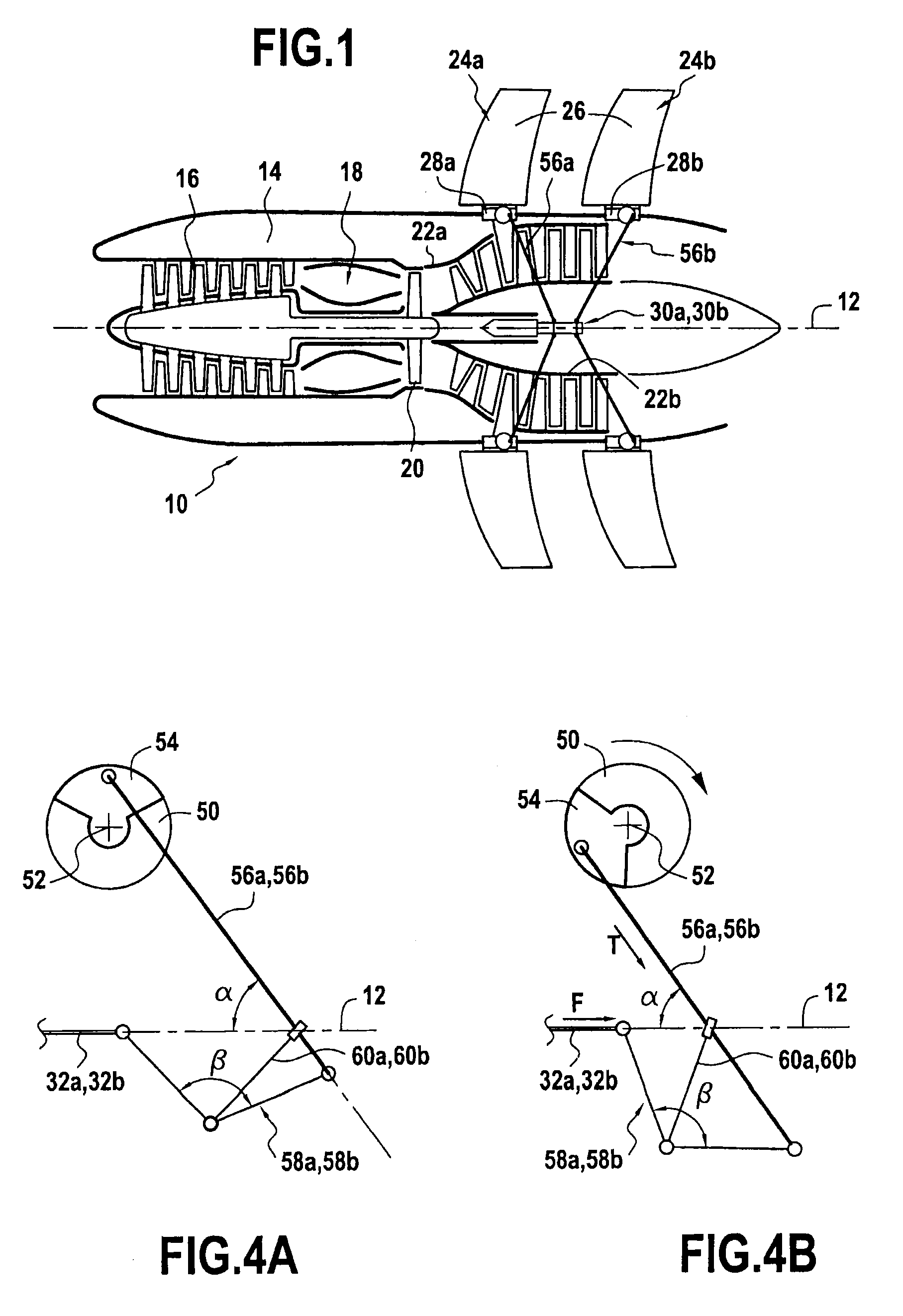
[0020]FIG. 1 shows very schematically an example of implementation of a dual propeller type aircraft turboprop.

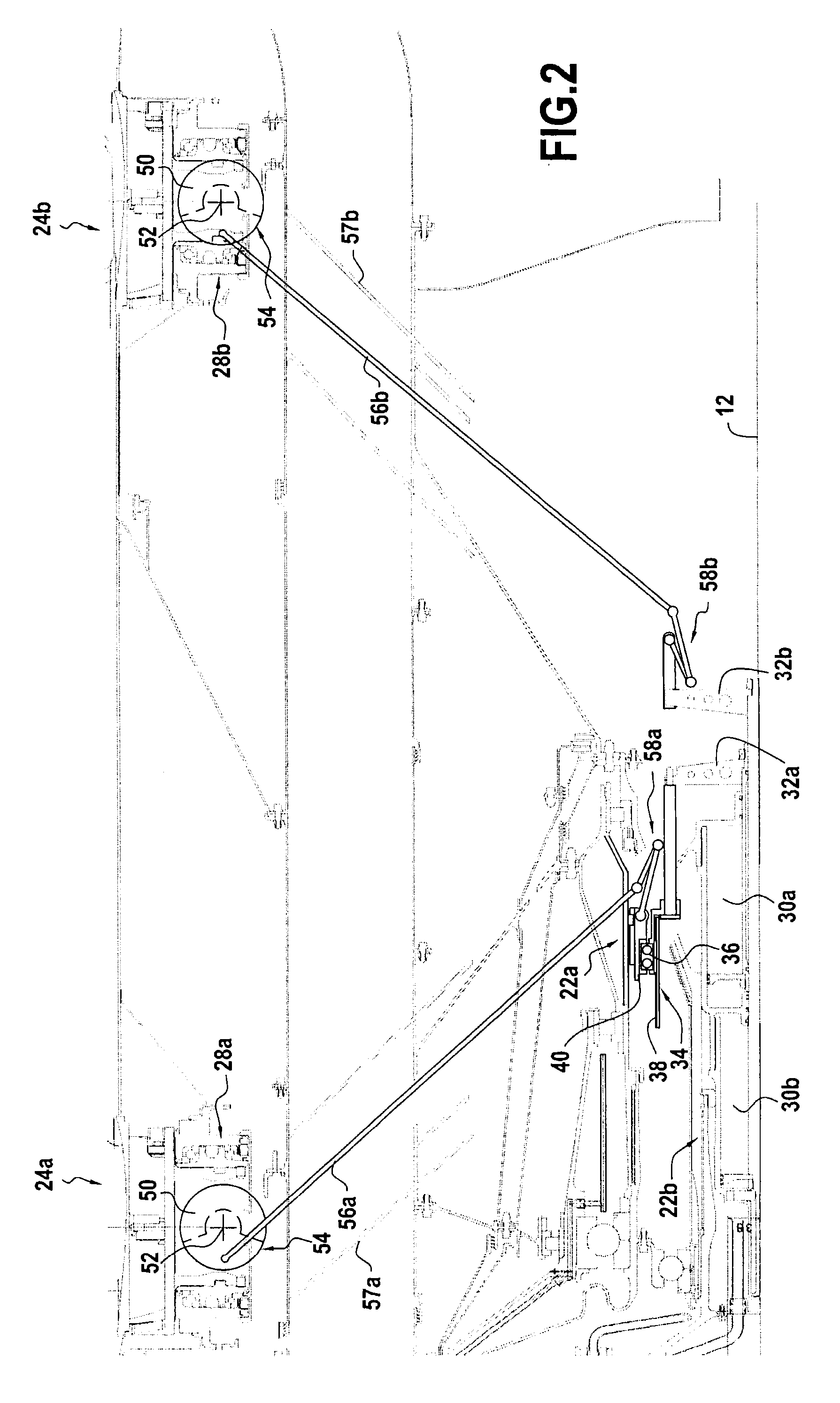
[0021]Such a turboprop is known and will therefore not be described in detail. The turboprop 10 includes in particular a longitudinal axis 12 and an annular nacelle 14 arranged coaxially about the longitudinal axis. The turboprop 10 also includes, from upstream to downstream, a compressor 16, a combustion chamber 18 and a turbine 20 having two counter-rotating rotors 22a, 22b, these different elements also being arranged coaxially about the longitudinal axis 12 of the turboprop.

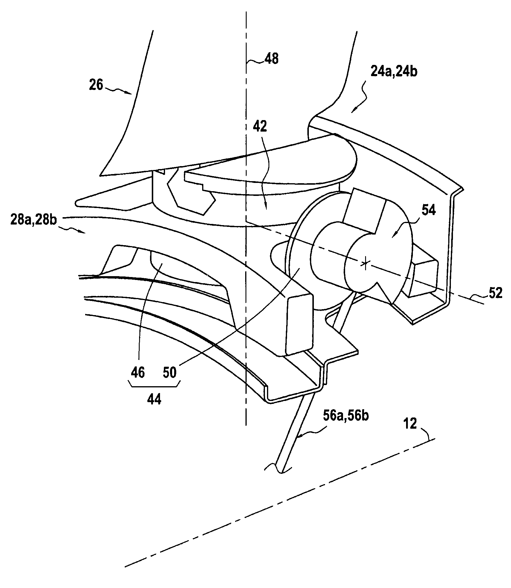
[0022]The turboprop 10 also includes an upstream (or front) set 24a and a downstream (or rear) set 24b of fan blades 26 having adjustable orientation. More precisely, the fan blades 26 of each set 24a, 24b mounted on a rotating ring 28a, 28b in the form of an annular platform centered on the longitudinal axis 12 of the turboprop.

[0023]Further, the fan blades 26 of each set are evenly spaced circumfer...


PUM


Abstract

A device for controlling orientation of fan blades of a turboprop including at least one set of fan blades having adjustable orientation attached in rotation to a rotating ring mechanically connected to a turbine rotor. Each blade of the set is coupled to a blade root support pivotably mounted on the rotating ring by a conical gear train including a first gear wheel attached to the blade root support and a second gear wheel attached to the rotating ring and bearing a counterweight that is eccentric with respect to its axis of rotation. A cylinder attached in rotation to the turbine rotor and a rod of which is connected to each counterweight through a connecting arm makes it possible to impart synchronous angular displacement to all the counterweights about the axis of rotation of their respective gear wheel.

Description

BACKGROUND OF THE INVENTION[0001]The present invention relates to the general field of turboprops comprising at least one set of variable orientation fan blades. It relates more particularly to orientation control of the fan blades of a dual propeller aircraft turboprop.[0002]In known fashion, a dual propeller aircraft turboprop includes a turbine with two counter-rotating rotors each driving one set of unducted fan blades. Reference can be made for example to document GB 2,129,502 which describes different embodiments of such a turboprop.[0003]In this kind of turboprop, the orientation of the fan blades of each set (the term pitch control is also used) constitutes one of the parameters making it possible to control the thrust of the turboprop.[0004]Different solutions have been proposed for controlling the fan blades of a given set. Reference can be made for example to French patent applications No. 09 53589 and 09 53591 filed by the Applicant on 29 May 2009. In these applications,...

Claims


Application Information

Patent Timeline
Patent Type & Authority Patents(United States)
IPC IPC(8): B64C11/06B64C11/32B64C11/48B64D27/02F01D7/00F02C6/20F04D29/32
CPCB64C11/325B64C11/48F01D7/00F02C6/206F04D29/323B64D2027/026Y02T50/671F05D2220/325B64D2027/005Y10T74/18784Y02T50/60
Inventor GALLET, FRANCOIS
Owner SN DETUDE & DE CONSTR DE MOTEURS DAVIATION S N E C M A
Learn More