

Wiper controller
a controller and wiper technology, applied in the field of wiper controllers, can solve the problem that the unwiped region is not unnecessarily smaller, and achieve the effect of not unnecessarily reducing the size of the unwiped area
- Summary
- Abstract
- Description
- Claims
- Application Information
AI Technical Summary
Benefits of technology
Problems solved by technology
Method used
Image

Examples
Embodiment Construction
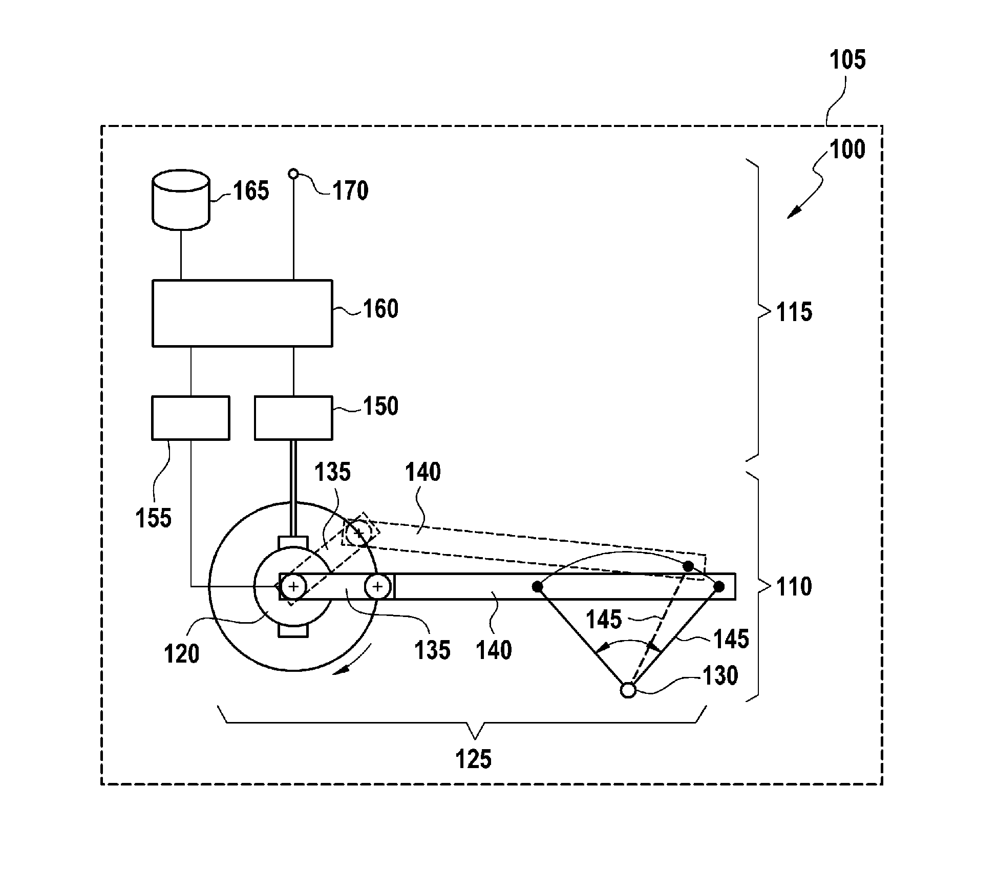
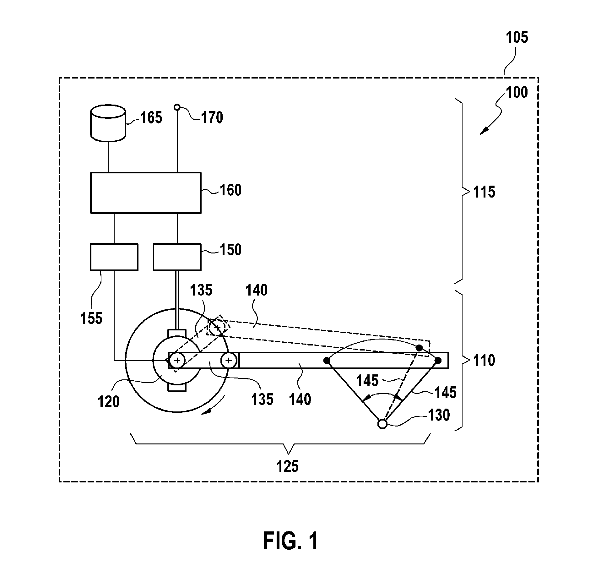
[0015]FIG. 1 shows a windshield wiping system 100 on board a motor vehicle 105. The windshield wiping system 100 comprises a windshield wiping device 110 and a controller 115. The windshield wiping device 110 comprises a drive device 120, a gear 125 and a wiper shaft 130. The gear 125 is formed by a drive crank 135, a linkage 140 and an output lever 145. The gear 125 can have further gear elements, in particular a worm gear (not illustrated) which steps down a rotational movement of the drive device 120 to the drive crank 135.
[0016]During operation of the windshield wiping device 110, the drive device 120 turns the drive crank 135, with the result that the pushrod 140 moves the output lever 145 about the wiper shaft 130 in an oscillating fashion in a circular segment. The direction in which the drive crank 135 is turned by the drive device 120 is irrelevant for this activation.
[0017]A wiper arm, which is connected to the wiper shaft 130 and guides a wiper blade over a window of the ...
PUM
 Abstract
Description
Claims
Application Information