Adjustable bracket assembly

a bracket assembly and adjustable technology, applied in the direction of pipeline expansion compensation, light support devices, building scaffolds, etc., can solve the problems of requiring more than one person to design and assemble these elements, and increasing the complexity of the process, so as to reduce the number of components, and reduce the cost of assembly. the effect of labor and parts

Active Publication Date: 2015-01-20
ADVANCED DESIGN MFG LLC
View PDF283 Cites 7 Cited by
  • Summary
  • Abstract
  • Description
  • Claims
  • Application Information

AI Technical Summary

Benefits of technology

[0010]The present invention relates to adjustable bracketing assemblies that can be employed readily over a wide array of bracketing applications to securely connect a variety of support members to external assemblies, while still satisfying the complement of requirements presented by dimensions, load factors, codes, and design preferences. Furthermore, the bracketing apparatus disclosed and claimed herein has been fashioned in such a manner as to maximize its utility over a broad range of applications, while minimizing the labor, parts and tools required for implementation. Since the apparatus is characterized by its universality and relative simplicity and ease of installation, it serves to fulfill both original and retrofit bracketing applications. The adjustability feature of the apparatus means that less “design customizing” is required for a given installation, thus leading to demonstrable cost savings.

Problems solved by technology

Designing and assembling these elements is ordinarily complicated since dimensions, load factors, code requirements, and aesthetics converge to present brackets which are labor and component intensive.
Moreover, with current technology, bracket assembly requires more than one person and is time consuming.
Many ready to assemble bracket assemblies utilize location dependent uprights or support members that multiply the effort needed to design and assembly the bracketing components and that intensify the complexity of the process.
Presently most bracketing assemblies are installed by the seller because of the complexity of assembling.
Thus, many bracketing assemblies are handled fully or most fully assembled which presents bulky cargo that takes up considerable amount of space and is difficult to transport.
Additionally, when one part of a piece of bracketing assembly is damaged, often the entire product must be returned instead of the damaged part.
For example, when an upright or support member fails or is defective, often the entire bracketing assembly must be replaced.

Method used


Image

  • Adjustable bracket assembly
  • Adjustable bracket assembly
  • Adjustable bracket assembly

Examples


Embodiment Construction

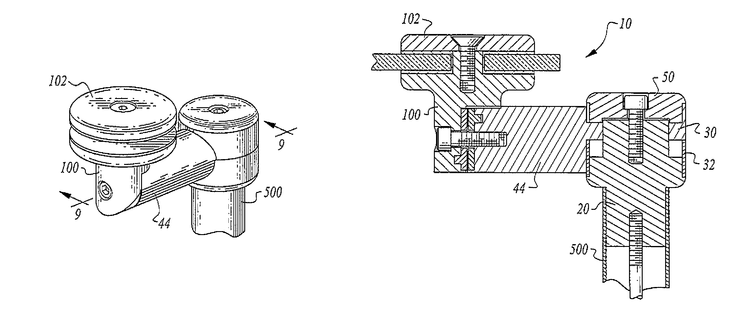
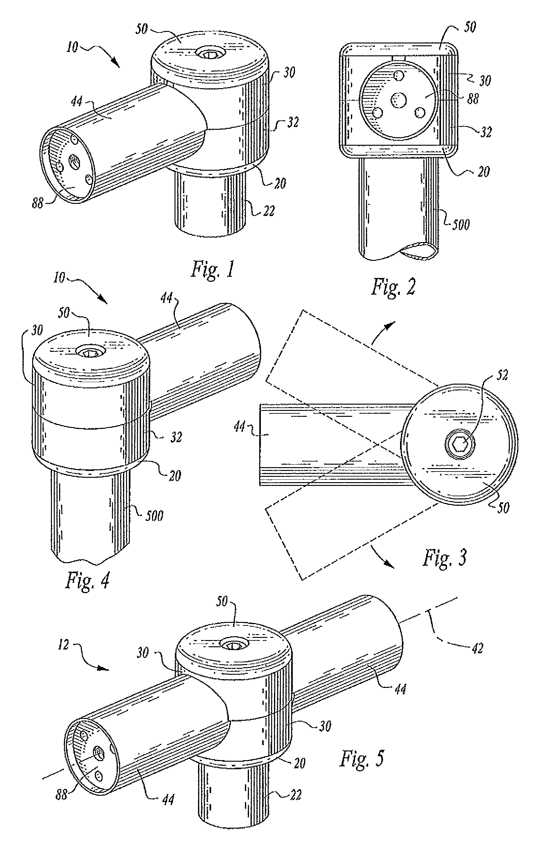
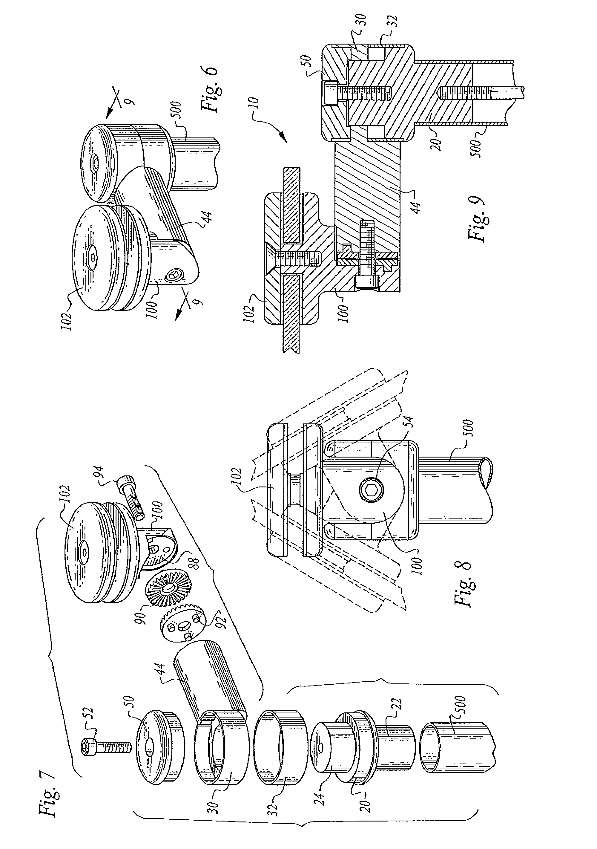
[0043]Referring now to FIGS. 1-21, embodiments of adjustable bracket assembly are illustrated and designated by reference numerals 10, 12 and 14.

[0044]Embodiments of the adjustable bracket assembly, 10, 12 and 14, include a cylindrical base 20 having a central longitudinal axis, a cylindrical base internal portion 24, and a cylindrical base external end 22, FIGS. 7, 9 and 11-12. The cylindrical base external end 22 includes a central threaded aperture sized to be received on a threaded fastener, when the cylindrical base external end is received within a elongated support element 500, FIGS. 7, 9 and 11-12.

[0045]Embodiments of the adjustable bracket assembly, 10 and 12, further include at least one cylindrical center portion 30 having a central longitudinal axis and an arm 44 affixed orthogonally to the central longitudinal axis, FIGS. 7, 9 and 11-12. Each arm 44 provides a rotatable head portion 100. The rotatable head portion 100 includes assembly for releasably connecting to and l...


PUM


Abstract

Adjustable bracket apparatus includes connector apparatus for mounting and securing external assemblies on at least one elongated support member, and allows positional adjustment of the secured external assembly along the elongated support member with up to 360 degree rotational positioning of the bracketing assembly about the elongated support member. An adjustable connector and locking assembly is disposed at the end of an arm element embodiment of the adjustable bracketing assembly providing 360 degree rotational positioning of the external assembly about the arm element and translation transverse to the axis of rotation relative to the arm.

Description

CROSS-REFERENCES TO RELATED APPLICATIONS[0001]None.STATEMENT REGARDING FEDERALLY SPONSORED RESEARCH OR DEVELOPMENT[0002]None.REFERENCE TO A MICRO-FICHE APPENDIX[0003]None.TECHNICAL FIELD[0004]This invention relates to ready-to-assemble components used in adjustable bracket assemblies for adapting to and connecting one or more substantially external assemblies defined by the particular utility of the overall assembly. Such ready-to-assemble components can be typically, but not exclusively, employed with a plurality of elongated, elongated oriented support members.BACKGROUND OF THE INVENTION[0005]Adjustable height supports and bracketing are well known in the art and typically comprise an upright or support member, some separate assembly for supporting a platform or similar assembly, apparatus for moving the separate assembly along the upright or support member, and an assembly for securing the upright or support member.[0006]Designing and assembling these elements is ordinarily compl...

Claims


Application Information

Patent Timeline
Patent Type & Authority Patents(United States)
IPC IPC(8): F16B7/10F16C11/00A47B96/06E04G5/06F16M13/00F21V35/00A47H1/10A47F5/08A47F5/00A47G29/00F21V21/00F16D1/12F16J15/52F16L51/02E04G3/00A47K1/00F16D3/00
CPCF21V21/00A47K1/00E04G3/00E04G5/06F16B7/0453F16C11/103F16D1/12F16D3/00F16J15/52F21V35/00Y10T403/32008Y10T403/32041Y10T403/32049Y10T403/32262Y10T403/32368A47F2010/065
Inventor MCGRATH, ANDREW, H.
Owner ADVANCED DESIGN MFG LLC
Why Eureka
Try Eureka