Vehicle lighting unit

a technology for vehicle lighting and lighting components, which is applied in the direction of fixed installation, lighting and heating equipment, lighting support devices, etc., can solve the problems of deteriorating reliability, affecting maintenance workability, and affecting the life of the drive circuit b>82/b>, so as to promote heat dissipation

Active Publication Date: 2015-01-27
STANLEY ELECTRIC CO LTD
View PDF3 Cites 6 Cited by
  • Summary
  • Abstract
  • Description
  • Claims
  • Application Information

AI Technical Summary

Benefits of technology

[0009]The presently disclosed subject matter was devised in view of these and other problems and features and in association with the conventional art. According to an aspect of the presently disclosed subject matter, there is provided a vehicle lighting unit that can promote the dissipation of heat from a semiconductor light emitting device such as an LED and heat from a drive circuit for the semiconductor light emitting device, both of which are the heat generation members, more effectively and / or differently as compared to the conventional lighting unit.
[0010]Furthermore, according to another aspect of the presently disclosed subject matter, there is provided a vehicle lighting unit that can not only promote dissipation of heat from a semiconductor light emitting device such as an LED and heat from a drive circuit for the semiconductor light emitting device, both of which are the heat generation members, more effectively but can also improve its maintenance workability as compared to the conventional lighting unit.
[0015]In a vehicle lighting unit made in accordance with principles of the presently disclosed subject matter, the semiconductor light emitting device and the drive circuit which are the heat generation members can be directly attached to the heat dissipation member to dissipate the generated heat. When compared with the conventional lighting unit in which the heat generated by the semiconductor light emitting device and the drive circuit is dissipated with the intervention of the metal substrate, the lighting unit of the presently disclosed subject matter can prevent the heat from the semiconductor light emitting device from being conducted to the drive circuit and can cause the heat to be directly conducted together with the heat from the drive circuit to the heat dissipation member, thereby effectively dissipating heat from the heat dissipation member. Therefore, the semiconductor light emitting device and the drive circuit can be effectively cooled by heat dissipation as compared to the conventional lighting unit.
[0024]Since the light source module can be removed from the holding member rearward, the semiconductor light emitting devices and / or the drive circuit can be easily replaced with new / replacement ones. This can enhance the maintenance workability as compared to the conventional lighting unit while the heat generated by the semiconductor light emitting devices and the drive circuit can be appropriately dissipated.

Problems solved by technology

As a result, there is a possibility that the lifetime of the drive circuit 82 and / or the reliability thereof may deteriorate.
This means that maintenance workability may deteriorate.

Method used


Image

  • Vehicle lighting unit
  • Vehicle lighting unit
  • Vehicle lighting unit

Examples


Embodiment Construction

[0035]A description will now be made below to vehicle lighting units of the presently disclosed subject matter with reference to the accompanying drawings in accordance with exemplary embodiments. Note that the following exemplary embodiments show a vehicle headlamp as an example of the vehicle lighting unit, but this is not limitative.

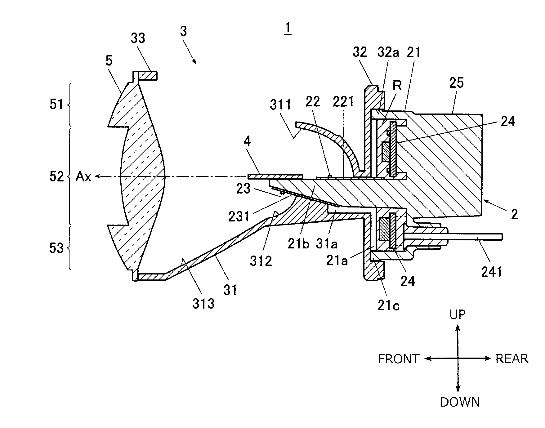
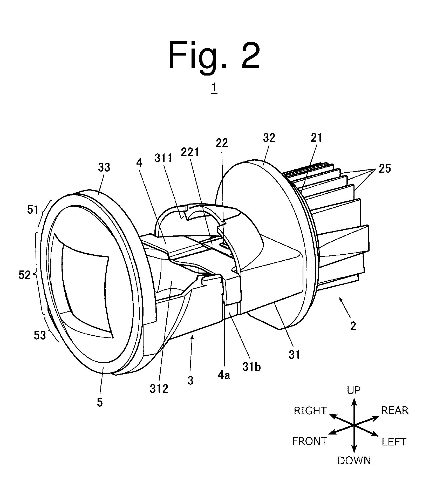
[0036]FIG. 2 is a perspective view illustrating a vehicle headlamp 1 according to an exemplary embodiment, FIG. 3 is an exploded perspective view illustrating the vehicle headlamp 1, FIG. 4 is a cross-sectional side view illustrating the vehicle headlamp 1, and FIG. 5 is a perspective view illustrating a holding member 3 included in the vehicle headlamp 1 when viewed from its rear side.

[0037]In the following description, the “forward (front),”“rearward (rear, back),”“left,”“right,”“upper,” and “lower” directions are based on a typical posture of an automobile vehicle body to which the vehicle lighting unit is installed unless otherwise specified, and ...


PUM


Abstract

A vehicle lighting unit can not only promote the dissipation of heat from a semiconductor light emitting device and a drive circuit for the device, both of which are the heat generation members, but also improve its maintenance workability. The vehicle lighting unit can include a light source module having a module main body. The module main body can include first and second semiconductor light emitting devices, drive circuits configured to drive and control the first and second semiconductor light emitting devices, and a heat dissipation fin for dissipating heat generated by the semiconductor light emitting devices and the drive circuits. Both the semiconductor light emitting devices and the drive circuit are directly attached to the module main body.

Description

[0001]This application claims the priority benefit under 35 U.S.C. §119 of Japanese Patent Application No. 2011-166163 filed on Jul. 29, 2011 and Japanese Patent Application No. 2011-166164 filed on Jul. 29, 2011, which are hereby incorporated in their entirety by reference.TECHNICAL FIELD[0002]The presently disclosed subject matter relates to a vehicle lighting unit for use in, for example, vehicle headlamps and the like.BACKGROUND ART[0003]Some conventional vehicle lighting units for use in a vehicle headlamp utilize a semiconductor light emitting device as a light source. Examples of such a semiconductor light emitting device include a light emitting diode (LED), a semiconductor laser, and the like. Recently, as the optical performance of such an LED is improved, the use of the semiconductor light emitting device like an LED as a light source for such a vehicle headlamp is increasing. Hereinafter, such a vehicle lighting unit will be described with taking a headlamp as an example...

Claims


Application Information

Patent Timeline
Patent Type & Authority Patents(United States)
IPC IPC(8): B60Q1/00F21S8/10
CPCF21S48/32F21S48/1159F21S48/1258F21S48/1388F21S48/145F21S48/1747F21S48/321F21S48/328F21S41/147F21S41/148F21S41/19F21S41/255F21S41/321F21S41/338F21S41/365F21S41/43F21S41/663F21S45/48F21S45/49F21S45/50F21S45/40
Inventor YATSUDA, YASUSHI
Owner STANLEY ELECTRIC CO LTD
Why Eureka
Try Eureka