Organic electroluminescent element

a technology of electroluminescent elements and organic materials, applied in the direction of organic semiconductor devices, thermoelectric devices, solid-state devices, etc., can solve the problems of chromaticity change tending to increase, problems that remain in order, etc., and achieve suppressed luminance and high luminance

Active Publication Date: 2015-01-27
SAMSUNG DISPLAY CO LTD
View PDF11 Cites 2 Cited by
  • Summary
  • Abstract
  • Description
  • Claims
  • Application Information

AI Technical Summary

Benefits of technology

[0011]According to the present invention, it is possible to obtain a white organic electroluminescent element with long-life in which deterioration in luminance is suppressed, which is a multiunit element capable of emitting high luminance that is important to an illumination light source.

Problems solved by technology

However, problems remain in order to realize sufficient improvement in a lifetime property in comparison with conventional main lighting, that is, fluorescent lamps.
However, Patent Literature 1 does not describe change in chromaticity and does not disclose clearly technologies for improving the lifetime of a multiunit element in which change in chromaticity tends to increase with the passage of time.

Method used


Image

  • Organic electroluminescent element
  • Organic electroluminescent element
  • Organic electroluminescent element

Examples


example 1

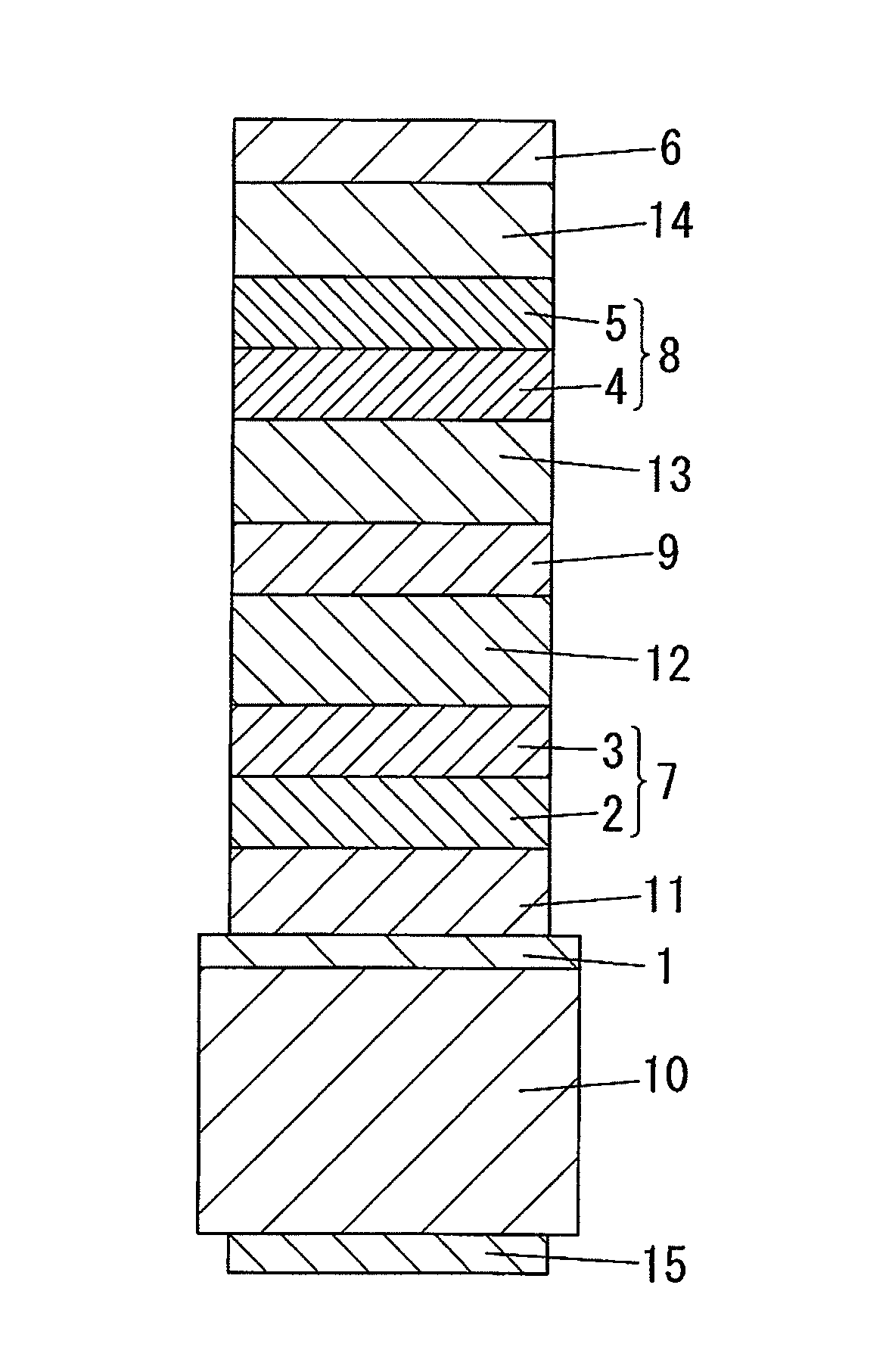
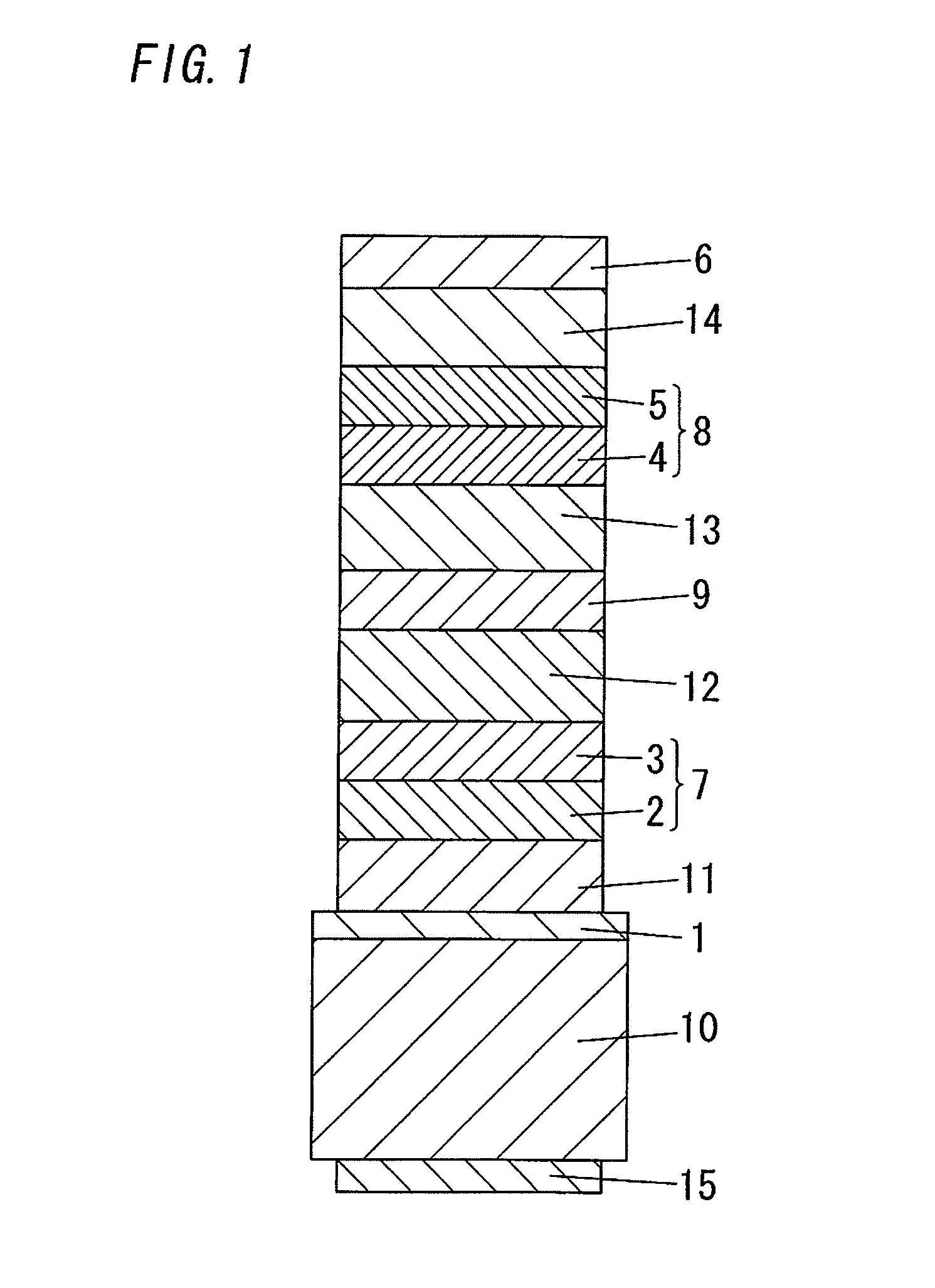
[0047]An organic electroluminescent element as shown in FIG. 1 was prepared. Specifically, a transparent electrode 1 was formed by depositing ITO with a thickness of 130 nm on a substrate 10 (a glass substrate). A first hole transporting layer 11, a blue fluorescent light-emitting layer 2 (containing BCzVBi as a blue fluorescent light-emitting material), a green fluorescent light-emitting layer 3 (containing TPA as a green fluorescent light-emitting material) and a first electron transporting layer 4 were further formed by a vapor deposition method with a thickness between 5 nm and 60 nm on the transparent electrode 1 in this order. Next, an intermediate layer 9 having a layer structure of Alq3 / Li2O / Alq3 / HAT-CN6 was stacked with a layer thickness of 15 nm. Then, a second hole transporting layer 13, a red phosphorescent light-emitting layer 4 (TAZ as a host material doped with Ir(piq)3 which is a red phosphorescent light-emitting material), a green phosphorescent light-emitting layer...

example 2

[0050]An organic electroluminescent element was prepared in the same manner as in Example 1, except that the film thickness (tR) of the red phosphorescent light-emitting layer 4 was set to 5 nm and the film thickness of the green phosphorescent light-emitting layer 5 was set to 35 nm.

[0051]With regard to the organic electroluminescent element obtained with the aforementioned manner, a result of a continuous drive with initial luminance of 3000 cd / m2 shows that the emission intensity of the green phosphorescence is increased relative to the emission intensity of the red phosphorescence and the luminance lifetime is prolonged.

example 3

[0052]An organic electroluminescent element was prepared in the same manner as in Example 1, except that the film thickness (tR) of the red phosphorescent light-emitting layer 4 was set to 10 nm and the film thickness of the green phosphorescent light-emitting layer 5 was set to 70 nm.

[0053]With regard to the organic electroluminescent element obtained with the aforementioned manner, a result of a continuous drive with initial luminance of 3000 cd / m2 shows that the emission intensity of the green phosphorescence is increased relative to the emission intensity of the red phosphorescence and the luminance lifetime is prolonged. Note that the drive voltage is increased with an increase in the film thickness (tG) of the green phosphorescent light-emitting layer 5.


PUM


Abstract

The present invention proposes a white organic electroluminescent element which is a multiunit element capable of emitting high intensity light that is important to a light source for lighting use, and can have an extended lifetime while suppressing deterioration in luminance. The organic electroluminescent element includes: a transparent electrode; and a first light-emitting unit including a blue fluorescent light-emitting layer containing a blue fluorescent light-emitting material; an intermediate layer; and a second light-emitting unit including a red phosphorescent light-emitting layer containing a red phosphorescent light-emitting material and a green phosphorescent light-emitting layer containing a green phosphorescent light-emitting material; and a reflecting electrode, wherein: the first and second light-emitting units are stacked having the intermediate layer interposed therebetween; and a film thickness (tR) of the red phosphorescent light-emitting layer and a film thickness (tG) of the green phosphorescent light-emitting layer satisfy a relation of 5*tR≦tG.

Description

TECHNICAL FIELD[0001]The present invention relates to an organic electroluminescent element.BACKGROUND ART[0002]Organic electroluminescent elements have attracted attention as a next-generation illumination light source because they enable planar light-emission and enable light emission of any color tone depending on the selection of light-emitting substances, and have been vigorously developed with the aim of practical use. In particular, research and development has been actively conducted especially with regard to technologies for extending the lifetime, methods for extending the lifetime by various design and technological developments of devices have been proposed. However, problems remain in order to realize sufficient improvement in a lifetime property in comparison with conventional main lighting, that is, fluorescent lamps.[0003]JP 2006-172763A (Patent Literature 1) discloses a method for improving all of whiteness, luminance efficacy, and a lifetime. In this method, a non-...

Claims


Application Information

Patent Timeline
Patent Type & Authority Patents(United States)
IPC IPC(8): H01L29/08H01L35/24H01L51/00H01L51/50H01L51/52
CPCH01L51/5203H01L51/5044H01L2251/5361H01L2251/558H10K59/32H10K2102/351H10K50/805H10K50/131
Inventor TSUJI, HIROYAKITTICHUNGCHIT, VARUTTIDE, NOBUHIRO
Owner SAMSUNG DISPLAY CO LTD
Why Eureka
Try Eureka