

Noise reduction system and method
- Summary
- Abstract
- Description
- Claims
- Application Information
AI Technical Summary
Benefits of technology
Problems solved by technology
Method used
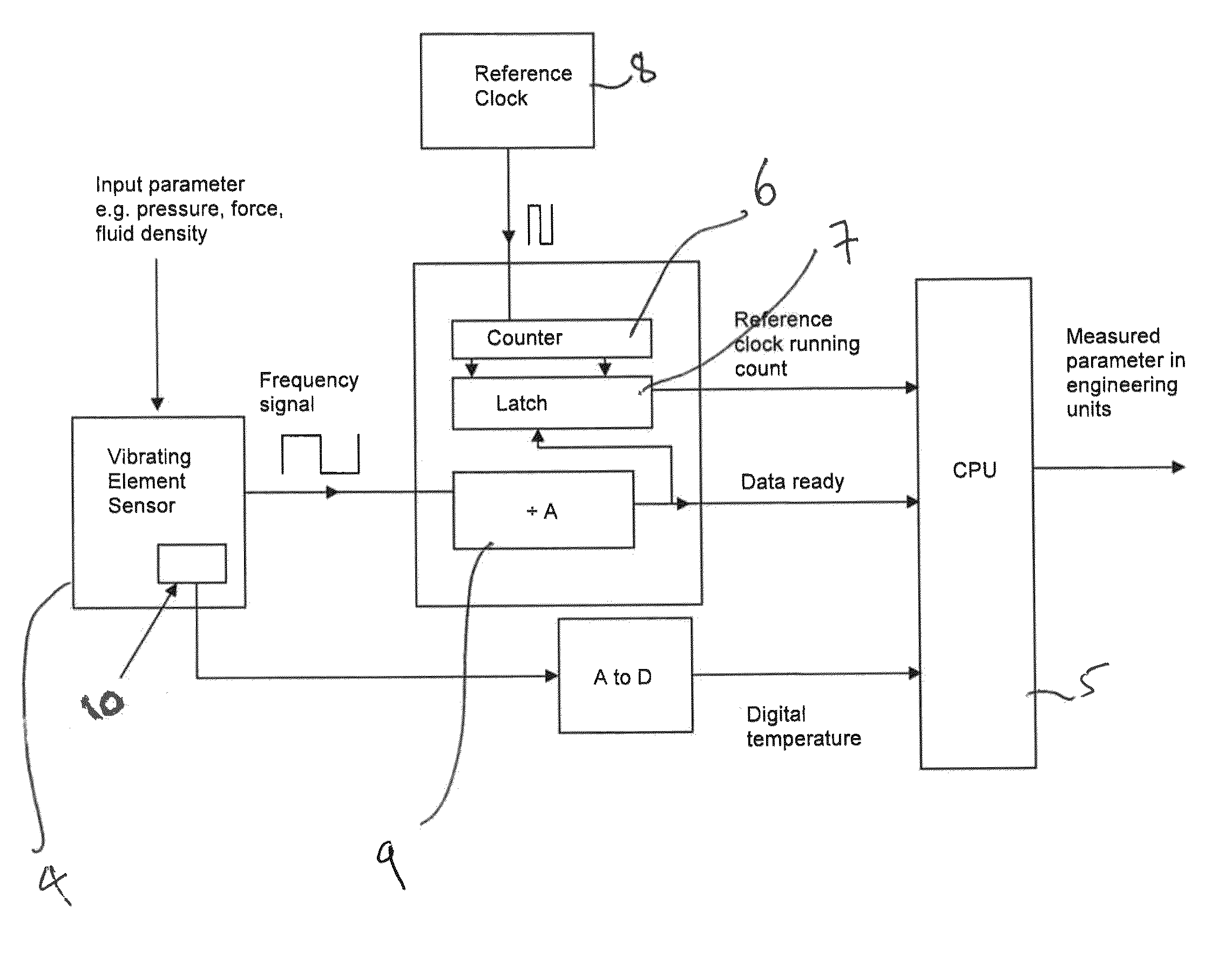
Image

Examples
Embodiment Construction
[0026]Preferred embodiments of the present invention aim to reduce the effect of noise while avoiding the need in the prior art to reduce the update rate (or response time), or to at least provide an alternative method and system for noise reduction.
[0027]The present invention provides a method and system set out in claims 1 and 8 to which reference should now be made. Preferred features of embodiments of the invention are set out in the dependent claims.
[0028]The inventors of the subject application have realised that the jitter noise on the edge of a sensed signal pulse is independent of the noise on other sensed signal pulses, and that the fact that the jitter noise on a sensor edge is independent of the noise on any other edge opens up the possibility of alternative sampling methods to reduce noise without significantly increasing the overall measurement time. Embodiments of the invention are particularly useful where one is measuring signal frequency when the received signal is...
PUM
 Abstract
Description
Claims
Application Information