Soil water and conductivity sensing system

a conductivity sensing and soil water technology, applied in the direction of resistance/reactance/impedence, instruments, measurement devices, etc., can solve the problems of inability to obtain reasonable field mean profile water contents, inability to meet the requirements of access tubes and sensors, and inability to accurately calibrate capacitance sensors in laboratory settings. the accuracy of np or tdr calibration is typically less than that of tdr

Inactive Publication Date: 2015-02-03
US SEC AGRI
View PDF4 Cites 29 Cited by
  • Summary
  • Abstract
  • Description
  • Claims
  • Application Information

AI Technical Summary

Problems solved by technology

Also, standard deviations of profile soil water content determined by capacitance sensors and by a down-hole quasi-TDR sensor were larger than those determined using the neutron probe or gravimetric sampling by hydraulic push probe, so much so that numbers of access tubes and sensors required to obtain reasonable field mean profile water contents was unaffordable.
Several field studies have shown that capacitance and quasi-TDR sensors exhibit unrealistic spatial variability when compared with NP and volumetric gravimetric sampling (Evett et al., 2009, ibid; Heng et al., 2002, Comparison of soil moisture sensors between neutron probe, Diviner 2000 and TDR under tomato crops.
Laboratory calibrations of capacitance sensors typically exhibit less accuracy than those from the NP or TDR.
Except for conventional TDR, laboratory calibrations did not, however, provide accurate soil water contents when used in the field (Evett et al., 2009, ibid).
November 2003), these calibrations are essentially unusable for accurate soil water content estimation using the capacitance sensors.
Existing capacitance systems are plagued by several problems.
The strength of the fringing field and the extent to which the EM field invades the soil outside the access tube is inversely proportional to the frequency, so attempts to avoid problems related to low frequencies are thwarted by the insensitivity of the measurement system that arises from using higher frequencies.
The EM field invades a uniform medium with a well defined shape, but soil is highly structured and often does not act like a uniform medium at the EM frequencies used in capacitance sensors.
Although at least one capacitance system now includes circuitry to measure soil BEC independently, no system exists that is free of temperature effects.
However, for a TDR probe in a soil the dielectric material between the probe rods is a complex mixture of air, water and soil particles giving rise to dielectric losses such that the apparent permittivity, ∈a, has both real and imaginary parts:
Although similar to TDR in attempting to determine a pulse travel time, most of the TDT methods do not accurately determine travel time due to problems with their algorithms for pulse reflection analysis (Evett et al., 2006, ibid).
That prevents those methods from finding the true travel time.

Method used


Image

  • Soil water and conductivity sensing system
  • Soil water and conductivity sensing system
  • Soil water and conductivity sensing system

Examples


example 1

[0070]This example utilizes the sensor including a cylindrical access tube with surface-mounted electrodes of this invention for use in TDR. This cylindrical geometry facilitates sensor installation at multiple depths in the soil profile. Variations in the tube and electrode geometries are tested in different media, including air, triethylene glycol, deionized water, sand, and clay loam. First, the sensor geometry is detailed; then, the construction procedure is described; finally, the results of sensor waveforms and dielectric measurements are compared across sensors and across media to assess sensor performance.

Access Tube Design and Geometrical Parameterization

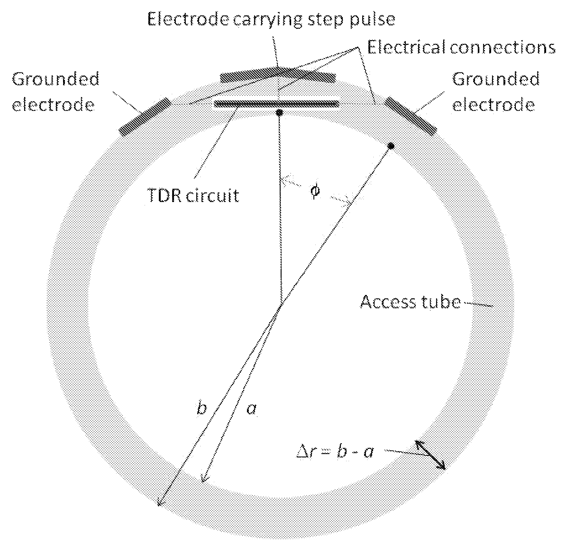
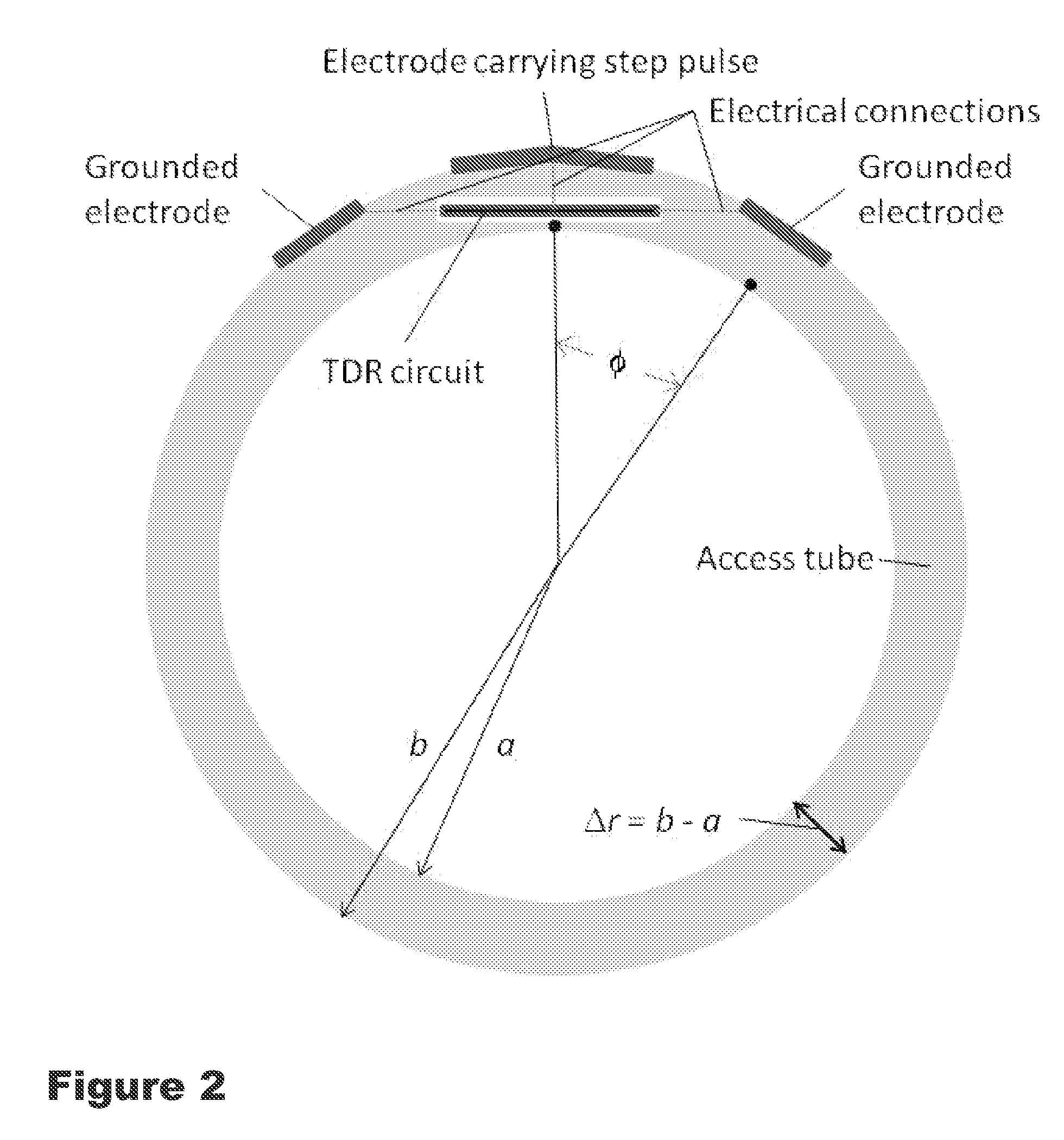
[0071]FIG. 2 shows a cross-section of the probe design with design parameters. The waveguide-on-access-tube TDR design comprises a cylindrical dielectric tube, with three electrodes on its surface that may or may not be connected to voltage ground or a source voltage. The probe can be fully described by the following variab...


PUM


Abstract

Soil water content and bulk electrical conductivity may be determined by time domain reflectometry at multiple depths in the soil such that the entire soil profile from the surface to a user-selected depth may be characterized. A short rise-time pulse is passed into an electrode and the reflected pulse is captured at multiple times. A waveform of reflection coefficient versus time is determined, which may be used to determine the pulse travel time, effective frequency and reflection coefficients at times necessary for the determination of the soil water content and bulk electrical conductivity.

Description

[0001]This application claims the benefit under 35 U.S.C. 1.19(e) of U.S. provisional No. 61 / 515,381, filed Aug. 5, 2011, the contents of which are incorporated by reference herein.BACKGROUND OF THE INVENTION[0002]1. Field of the Invention[0003]The invention is drawn to a method and apparatus for sensing the soil water content and soil bulk electrical conductivity (BEC). Moreover, the water content and BEC may be determined to arbitrary depths in discrete intervals for managing the irrigation of plants, studying and managing environmental interventions and any other applications.[0004]2. Description of the Prior Art[0005]Soil water content and bulk electrical conductivity have both been sensed by electronic systems that measure the electrical response to an imposed electromagnetic (EM) signal. Such systems differ in the nature of the imposed EM signal, the nature of the measured electrical response, and the nature of the electronic circuitry used and its ability to measure various a...

Claims


Application Information

Patent Timeline
Patent Type & Authority Patents(United States)
IPC IPC(8): G01R27/04
CPCG01N27/223G01N33/246
Inventor EVETT, STEVEN R.ANDERSON, SCOTT K.CASANOVA, JOAQUIN J.SCHWARTZ, ROBERT C.
Owner US SEC AGRI
Why Eureka
Try Eureka