Receiver and method for determining a time measure depending on a time of arrival of a pulse signal

a pulse signal and time measurement technology, applied in the field of wireless ultrawideband (uwb) ranging and localization systems, can solve the problems of relatively low time/distance resolution, large time of arrival estimation error, and difficult to achieve the effect of high resolution and/or efficient implementation, and poor time resolution

Inactive Publication Date: 2015-02-03
FRAUNHOFER GESELLSCHAFT ZUR FOERDERUNG DER ANGEWANDTEN FORSCHUNG EV
View PDF20 Cites 2 Cited by
  • Summary
  • Abstract
  • Description
  • Claims
  • Application Information

AI Technical Summary

Benefits of technology

[0016]The basic idea underlying the present invention is that the above-mentioned higher resolution and / or efficient implementation can be achieved when a variable and controllable integration window is provided, extending from a starting point to an integrator sampling point, and the integration window is controlled in a time-successive way so that the sampling points of successive integration windows are changed by a time delay from a current integration window to a later integration window, wherein the time delay is smaller than half of the integration window. By this measure, a poor time resolution and a corresponding relatively large time of arrival estimation error can be prevented with relatively low effort, thereby realizing an improved concept of an efficient receiver.
[0017]According to a further embodiment of the present invention, the integrator comprises a time delay unit controlled by the integrator controller, wherein the time delay unit is configured for delaying the pulse signal by increasing time delays over several successive pulses based on a control signal output by the integrator controller. This measure enables to controllably increase the time resolution, which essentially depends on how often time delays have been successively introduced.

Problems solved by technology

However, the same properties provide design challenges, such as high sampling rate, synchronization and power control.
Reception of UWB signals poses challenges in the receiver structure.
However, a general problem of known receivers is that they are characterized by relatively low time / distance resolution and have a relatively complex structure.

Method used


Image

  • Receiver and method for determining a time measure depending on a time of arrival of a pulse signal
  • Receiver and method for determining a time measure depending on a time of arrival of a pulse signal
  • Receiver and method for determining a time measure depending on a time of arrival of a pulse signal

Examples


Embodiment Construction

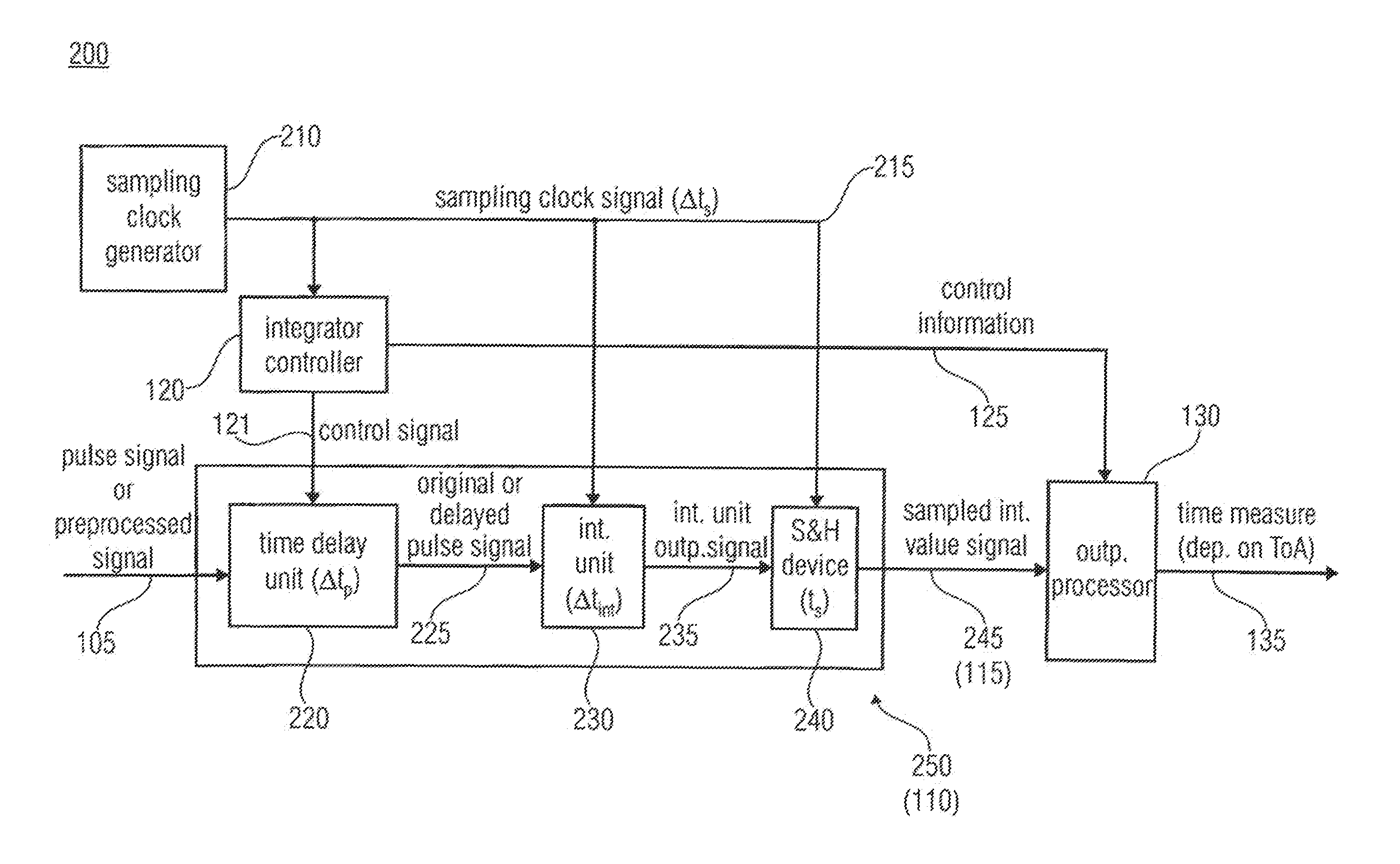
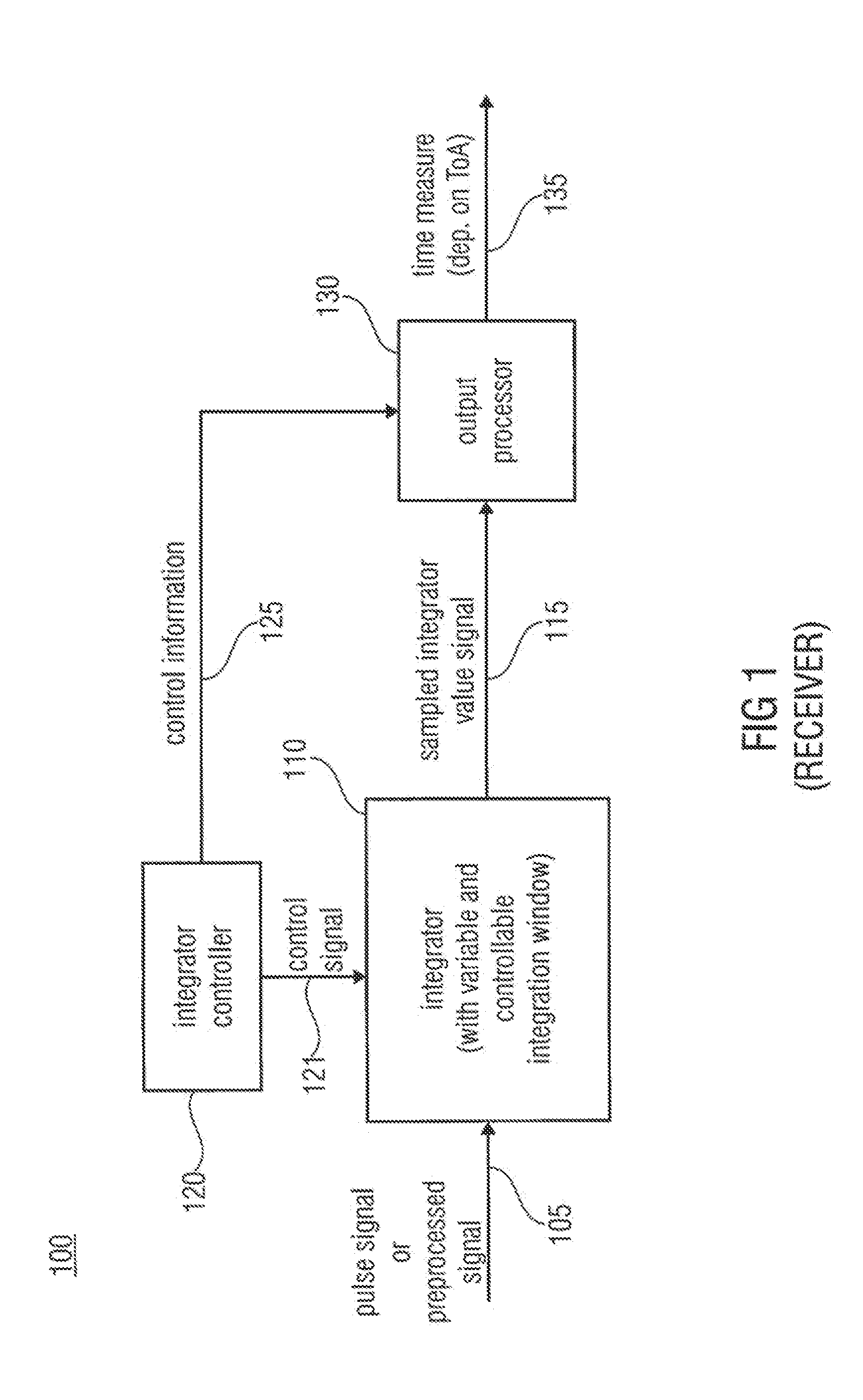
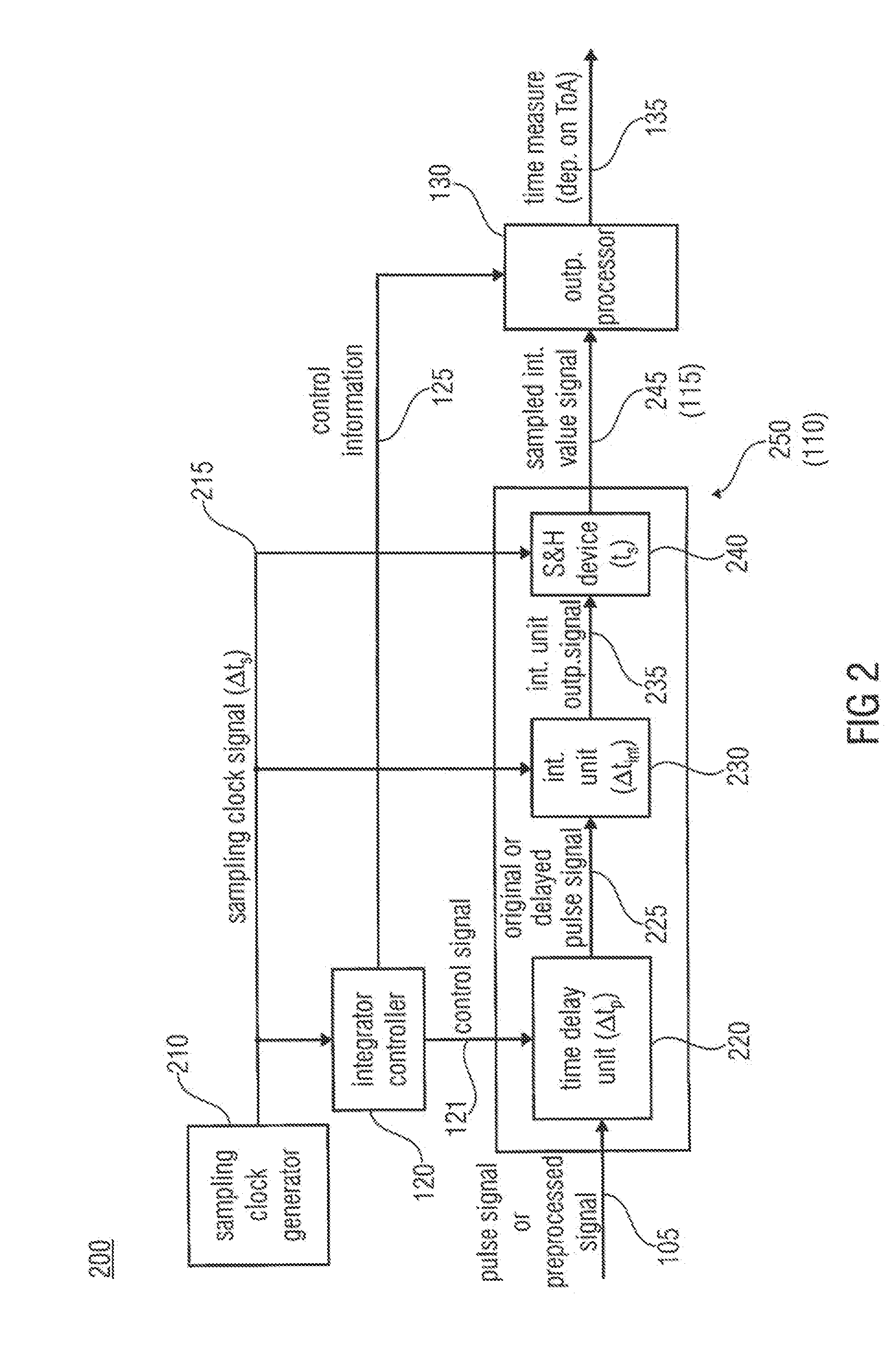
[0042]FIG. 1 shows a block diagram of an embodiment of the receiver 100 for determining a time measure depending on a time of arrival of a pulse signal 105. The pulse signal 105 may be transmitted from a transmitter having a sequence of pulses. Here, each pulse of the sequence of pulses may represent a band-limited pulse such as a UWB pulse. The receiver 100 is configured to receive the transmitted pulse signal or a preprocessed version (e.g. a squared version) thereof. As shown in FIG. 1, the receiver 100 comprises an integrator 110, an integrator controller 120 and an output processor 130. In particular, the integrator 110 has a variable and controllable integration window, extending from a starting point to an integrator sampling point. The integrator controller 120 may be configured for controlling the integration window in a time-successive way so that the sampling points of successive integration windows are changed by a time delay from a current integration window to a later ...


PUM


Abstract

A receiver for determining a time measure depending on a time of arrival of a pulse signal having a sequence of pulses from a transmitter includes an integrator having a variable and controllable integration window, extending from a starting point to an integrator sampling point, an integrator controller for controlling the integration window in a time-successive way so that the sampling points of successive integration windows are changed by a time delay from a current integration window to a later integration window, wherein the time delay is smaller than half of the integration window, and an output processor for generating the time measure as an indication indicating which later integration window has a sampled integrator value exceeding a threshold or being larger than a sampled integrator value for a timely preceding or timely succeeding integration window.

Description

CROSS-REFERENCE TO RELATED APPLICATIONS[0001]This application claims priority to European Patent Application No. 10175811.8 filed Sep. 8, 2010.BACKGROUND OF THE INVENTION[0002]Embodiments of the present invention relate to wireless ultra-wideband (UWB) ranging and localization systems, and in particular, to a concept for determining a time measure depending on a time of arrival of a pulse signal having a sequence of pulses from a transmitter. Further embodiments of the present invention relate to an energy receiver architecture for UWB ToA (time of arrival) estimation.[0003]Ultra-wideband Impulse Radio (UWB-IR) has several unique characteristics that make it a promising candidate for future wireless localization. The large absolute bandwidth, in the US from 3.1 to 10.6 GHz and in Europe from 6 to 8.5 GHz, corresponds to a very fine time resolution in the order of hundreds of picoseconds which translates to spatial resolution in the order of centimeters. The very fine time resolution...

Claims


Application Information

Patent Timeline
Patent Type & Authority Patents(United States)
IPC IPC(8): H03K9/00H04L1/02G01S11/02H04B1/7163
CPCG01S11/02H04B1/71637
Inventor PIETRZYK, MICHAL MIROSLAWVAN DER GRUEN, THOMAS
Owner FRAUNHOFER GESELLSCHAFT ZUR FOERDERUNG DER ANGEWANDTEN FORSCHUNG EV
Why Eureka
Try Eureka