Autoanalyzer and probe elevating method

a technology which is applied in the field of autoanalyzer and probe elevating method, can solve the problems of deteriorating precision upon dispensing the examined sample, thin air layer, etc., and achieve the effect of high precision

Active Publication Date: 2015-02-10
TOSHIBA MEDICAL SYST CORP
View PDF10 Cites 0 Cited by
  • Summary
  • Abstract
  • Description
  • Claims
  • Application Information

AI Technical Summary

Benefits of technology

[0016]An object of the invention is to provide an autoanalyzer and a method of elevating a probe for dispensing an examined sample with high precision.

Problems solved by technology

As a result, a problem arises in that the air layer is thinned, and a problem arises in that the pressure transmission medium is mixed with the dummy examined sample formed during the first dispensing operation to thereby be diluted because of the thinned air layer.
Due to such problems, when the number of the dispensing operations of the same examined sample increases, a problem arises in that the precision upon dispensing the examined sample deteriorates.

Method used


Image

  • Autoanalyzer and probe elevating method
  • Autoanalyzer and probe elevating method
  • Autoanalyzer and probe elevating method

Examples


Embodiment Construction

[0036]Hereinafter, an autoanalyzer according to an embodiment of the invention will be described with reference to FIGS. 1 to 13.

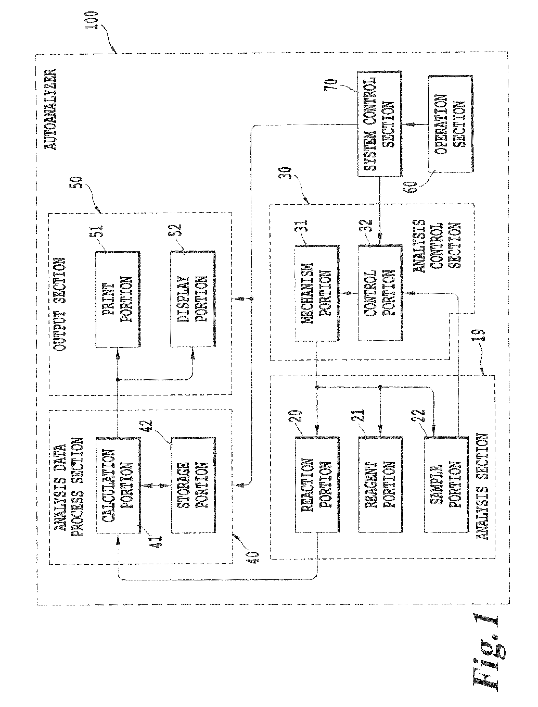
[0037]FIG. 1 is a block diagram showing a configuration of the autoanalyzer according to the embodiment of the invention. An autoanalyzer 100 includes an analysis section 19 which measures a measurement item selectively input for each examined sample or calibrator of various measurement items; an analysis control section 30 which controls a measurement operation of the analysis section 19; an analysis data process section 40 which processes analysis signals output from the analysis section 19 to generate analysis data; an output section 50 which outputs analysis data from the analysis data process section 40; an operation section 60 which inputs various command signals, a measurement item selection input for each examined sample or an analysis condition setting for each measurement item; and a system control section 70 which generally controls the above-de...


PUM

PropertyMeasurementUnit
depthaaaaaaaaaa
liquid surface detectoraaaaaaaaaa
speedaaaaaaaaaa

Abstract

An autoanalyzer includes a measurement unit which measures a reaction liquid produced by an interaction between a reagent and an examined sample contained in a reaction container, a sample probe which sucks the examined sample from a sample container and discharges the examined sample to the reaction container, a probe elevating arm which elevates the sample probe with respect to the sample container, and a control unit which controls the probe elevating arm so that a speed at which the sample probe enters a liquid surface of the examined sample to perform an n-th suction operation (n≧2) of the examined sample is slower than a speed at which the sample probe enters the liquid surface of the examined sample to perform a first suction operation of the examined sample.

Description

CROSS REFERENCE TO RELATED APPLICATIONS[0001]This is a Continuation Application of PCT Application No. PCT / JP2007 / 051198, filed Jan. 25, 2007, which was published under PCT Article 21(2) in Japanese.[0002]This application is based upon and claims the benefit of priority from prior Japanese Patent Application No. 2006-018646, filed Jan. 27, 2006, the entire contents of which are incorporated herein by reference.BACKGROUND OF THE INVENTION[0003]1. Field of the Invention[0004]The present invention relates to an autoanalyzer for analyzing components contained in a liquid and a dispensing method thereof, and more particularly, to an autoanalyzer for automatically measuring components contained in a body fluid by dispensing the body fluid such as human blood or urine and a probe elevating method thereof.[0005]2. Description of the Related Art[0006]An autoanalyzer measures a light transmitting amount to check a variation in a color tone and the like generated during a reaction of a mixed l...

Claims


Application Information

Patent Timeline
Patent Type & Authority Patents(United States)
IPC IPC(8): C12Q1/68G01N35/00G01N35/10
CPCG01N35/1011G01N35/1009G01N35/1016G01N2035/00277G01N2035/1025G01N35/10
Inventor OONUMA, TAKEHIKO
Owner TOSHIBA MEDICAL SYST CORP
Why Eureka
Try Eureka