Device for generating an adjustable bandgap reference voltage with large power supply rejection rate

a reference voltage and power supply technology, applied in the direction of electrical variable regulation, process and machine control, instruments, etc., can solve the problems of circuits requiring a relatively high power supply voltage and occupying a large silicon area

Active Publication Date: 2015-02-10
STMICROELECTRONICS (ROUSSET) SAS
View PDF27 Cites 3 Cited by
  • Summary
  • Abstract
  • Description
  • Claims
  • Application Information

AI Technical Summary

Benefits of technology

[0027]The common-gate setup (in which the input signal drives the source of a MOS transistor) which is distinguished from a common-source setup (in which the signal drives a gate of a MOS transistor) makes it possible to decrease the input impedance since a source instead of a gate is driven, thereby making it possible in particular to improve the PSRR parameter.
[0028]Moreover, a folded setup of the first stage of the amplifier, in which the branches containing the PMOS transistors are connected between the terminals of the core and a reference voltage, for example earth, is distinguished from a stacked setup in which the transistors of the first stage are stacked with the transistors of the feedback stage and the transistors of the core, and thus makes it possible to operate under a minimum power supply voltage equal to the sum of a drain-source voltage of a MOS transistor and of a diode voltage, i.e. about 0.9 volts. The use of PMOS transistors also allows a bias of the first stage “through the bottom”, that is to say a flow of the bias current towards earth.
[0038]Such an embodiment makes it possible to reduce the voltage offset of the amplifier, thereby favouring the equalization of the voltages across the terminals of the core.

Problems solved by technology

This consequently results in a considerable occupied silicon area.
However, such a circuit exhibits the drawback of requiring a relatively high power supply voltage because of the presence of cascoded current mirrors, stacked between the power supply terminal and the core.

Method used


Image

  • Device for generating an adjustable bandgap reference voltage with large power supply rejection rate
  • Device for generating an adjustable bandgap reference voltage with large power supply rejection rate
  • Device for generating an adjustable bandgap reference voltage with large power supply rejection rate

Examples


Embodiment Construction

[0018]Before addressing the illustrated embodiments in detail, various embodiments and advantageous features thereof will be discussed generally in the following paragraphs.

[0019]According to one embodiment, there is proposed a generator of a reference voltage of the bandgap type capable of operating under a low power supply voltage, with a reduced silicon area, and exhibiting a large PSRR parameter (“Power Supply Rejection Ratio”). It is recalled that the PSRR parameter is the ratio of the variation of the power supply voltage to the corresponding variation of the bandgap voltage delivered.

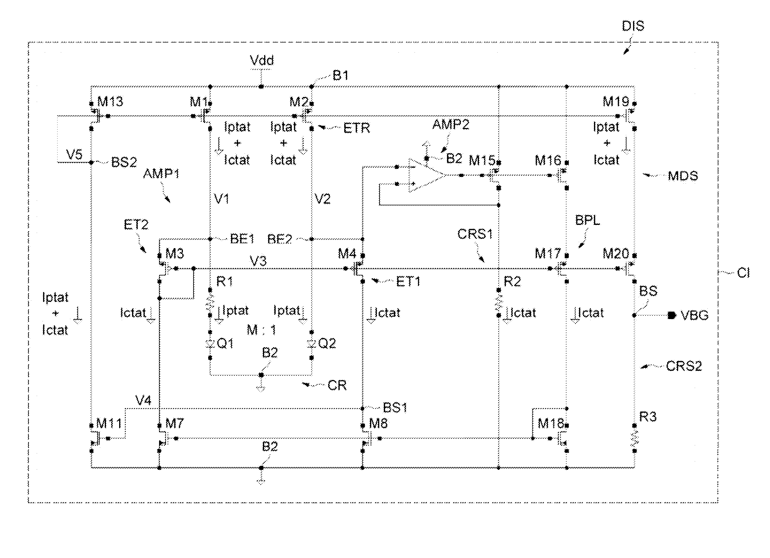
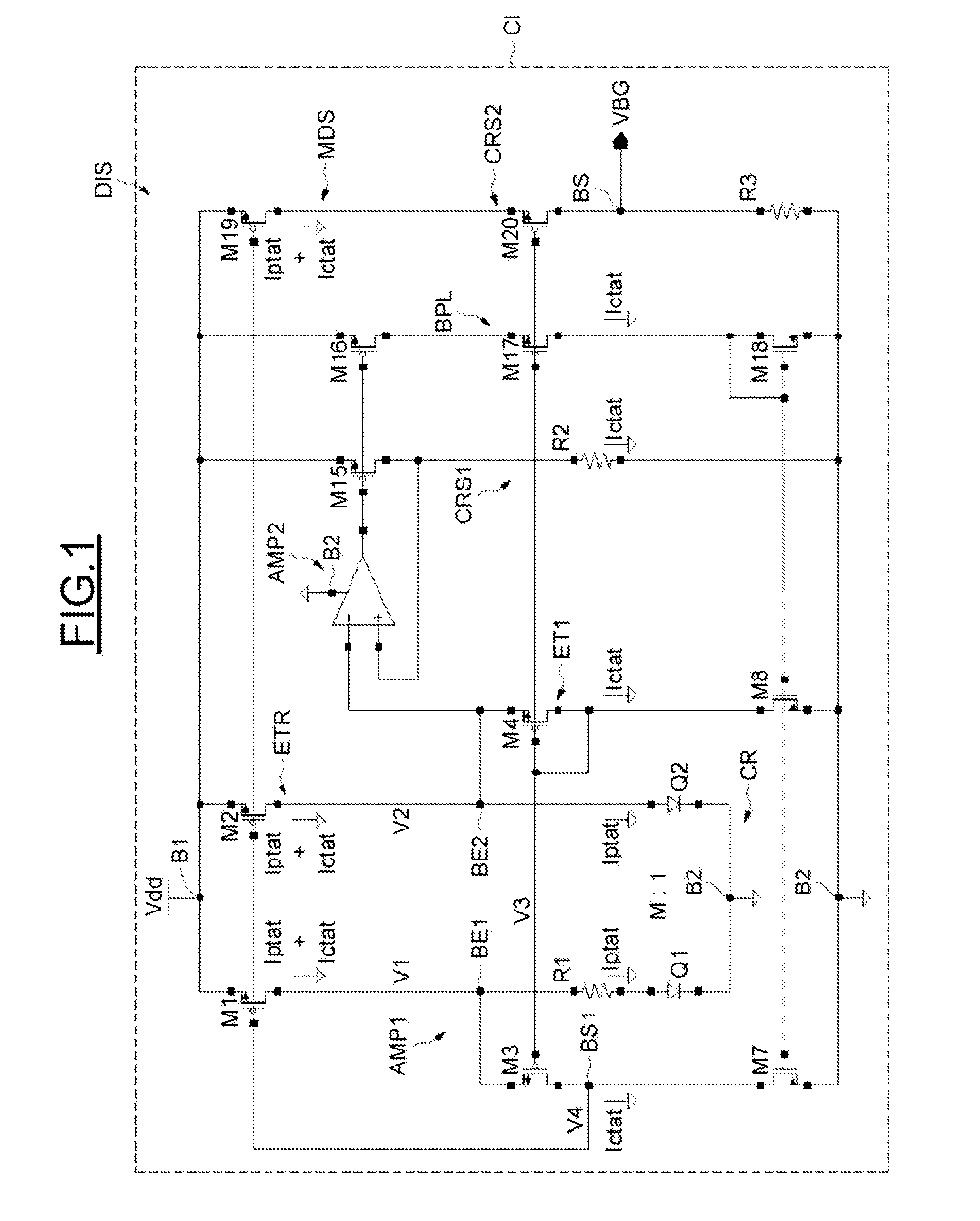
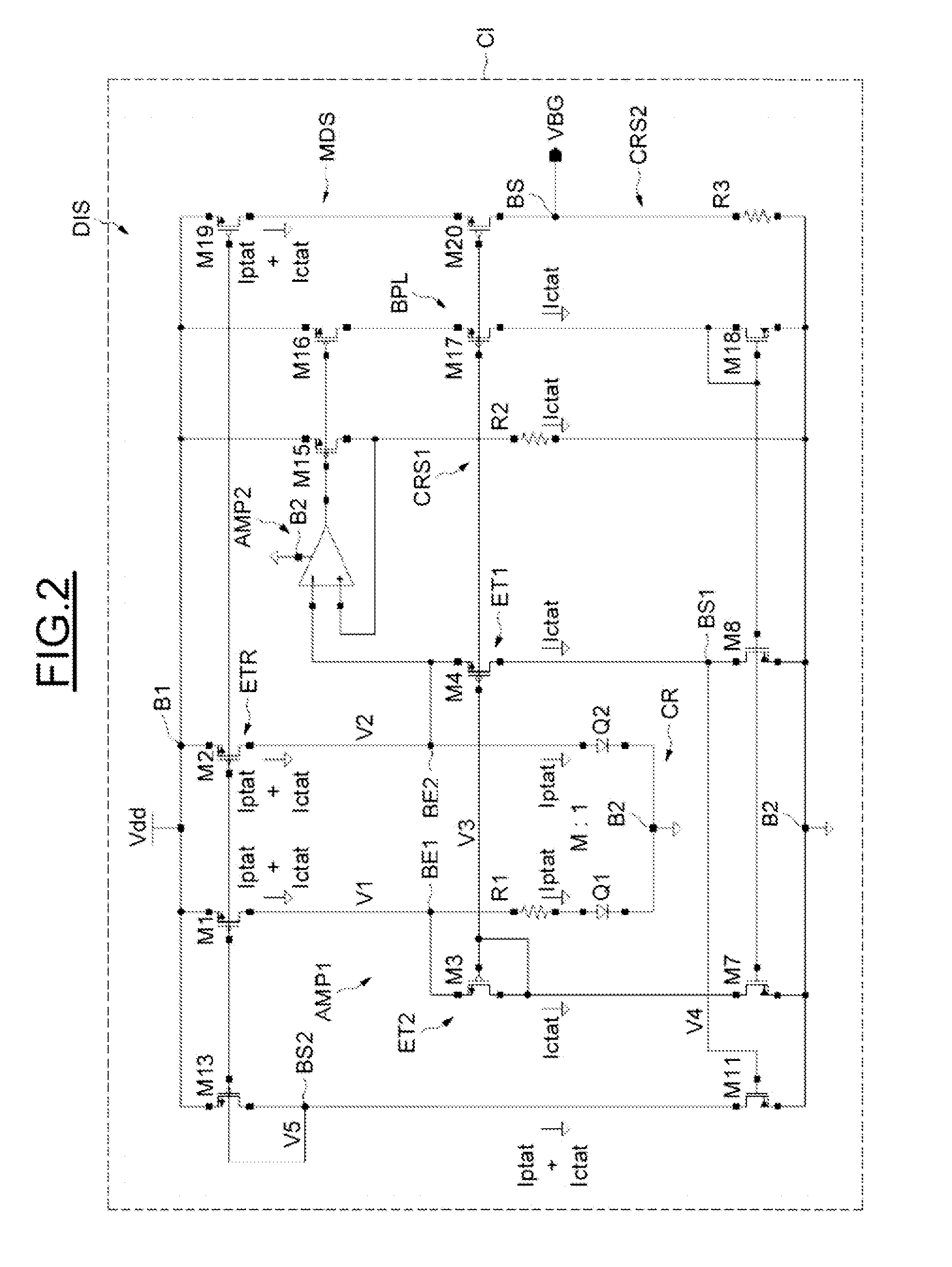
[0020]According to one aspect, there is proposed a device for generating a bandgap reference voltage comprising first means for generating a current proportional to absolute temperature, these first generating means comprising first processing means connected to the terminals of a core and designed to equalize the voltages across the terminals of the core. The device also comprises second means f...


PUM


Abstract

An adjustable bandgap reference voltage includes a first circuit for generating IPTAT, a second circuit for generating ICTAT, and an output module configured to generate the reference voltage. The first circuit includes a first amplifier connected to terminals of a core for equalizing voltages across the terminals, where the first amplifier has a first stage that is biased by the current inversely proportional to absolute temperature and is arranged according to a folded setup with first PMOS transistors arranged according to a common-gate setup. The first circuit also includes a feedback stage with an input connected to the first amplifier output. The feedback stage output is connected to the first stage input and to a terminal of the core. The second circuit includes a follower amplifier connected to a terminal of the core and separated from the first amplifier and the output module is connected to the feedback stage.

Description

CROSS-REFERENCE TO RELATED APPLICATIONS[0001]This application claims the priority benefit of French patent application number 1154266, filed May 17, 2011, entitled “Low Voltage Bandwith Improved Power Supply Rejection,” which is hereby incorporated by reference to the maximum extent allowable by law.TECHNICAL FIELD[0002]The invention relates to the generation of a so-called bandgap reference voltage. A bandgap reference voltage is a voltage which is substantially independent of temperature, and devices generating such reference voltages are widely used in integrated circuits.BACKGROUND[0003]Generally, a circuit generating a bandgap voltage delivers an output voltage in the vicinity of 1.25 volts, near the bandgap value of silicon at the temperature of 0 degrees Kelvin which is equal to 1.22 eV. In certain circuits, the value of the reference voltage delivered may be adjusted by the value of a resistor or a resistance ratio. One then speaks of an adjustable bandgap reference voltage....

Claims


Application Information

Patent Timeline
Patent Type & Authority Patents(United States)
IPC IPC(8): G05F3/16G05F3/20G05F3/30
CPCG05F3/30G05F1/625
Inventor FORT, JIMMYSOUDE, THIERRY
Owner STMICROELECTRONICS (ROUSSET) SAS
Why Eureka
Try Eureka