Unlock instant, AI-driven research and patent intelligence for your innovation.

Radiation image detecting device and method for controlling the same

a detection device and image technology, applied in the field of radioation image detection devices, can solve the problems of operator's likely to miss the timing of shooting, noise in the output of electrical components, and increased power consumption

Active Publication Date: 2015-02-10
FUJIFILM CORP
View PDF15 Cites 7 Cited by
  • Summary
  • Abstract
  • Description
  • Claims
  • Application Information

AI Technical Summary

Benefits of technology

The present invention is about a device and method for detecting radiation. The invention uses a sensor that is able to detect the radiation and create an image. However, sometimes this sensor can create false detections, which means that it can pick up signals that are not actually caused by radiation. The invention solves this problem by disabling the sensor when it detects high levels of noise that can lead to false detections. This prevents the device from detecting things that are not actually caused by radiation, which improves the accuracy of the detection.

Problems solved by technology

Generally, an output from an electrical component is affected by noise caused by an internal factor of the component itself or an external factor such as ambient environment.
For example, when a subject or radiological technologist bumps into the X-ray image detection device inadvertently, vibration or shake caused by the impact causes noise.
Power consumption increases when the false detection induces unnecessary operations of the X-ray image detection device.
Because the X-ray imaging cannot be performed during the irradiation detection operation, an operator is likely to miss the timing for shooting.
Moreover, the imaging control device and a device (for example, a console) for setting imaging conditions, both connected to the X-ray image detection device, may go through unnecessary operations as if the image capture has been performed.
Accordingly, burdensome operations such as resetting the imaging conditions are necessary.
This may cause medical malpractice.
As a result, the false detection occurs.
In the method of the U.S. Pat. No. 6,797,960, there is a possibility of the false detection when the bias current varies due to noise.
All of the methods described in the U.S. Patent Application Publication No. 2003 / 0086523, the U.S. Pat. No. 6,797,960, and the U.S. Patent Application Publication No. 2010 / 0054405 are susceptible to noise, so these methods are at increased risk of erroneously detecting the start of the X-ray irradiation.
However, none of the above describes how to prevent the false detection caused by noise.

Method used


Image

  • Radiation image detecting device and method for controlling the same
  • Radiation image detecting device and method for controlling the same
  • Radiation image detecting device and method for controlling the same

Examples


Embodiment Construction

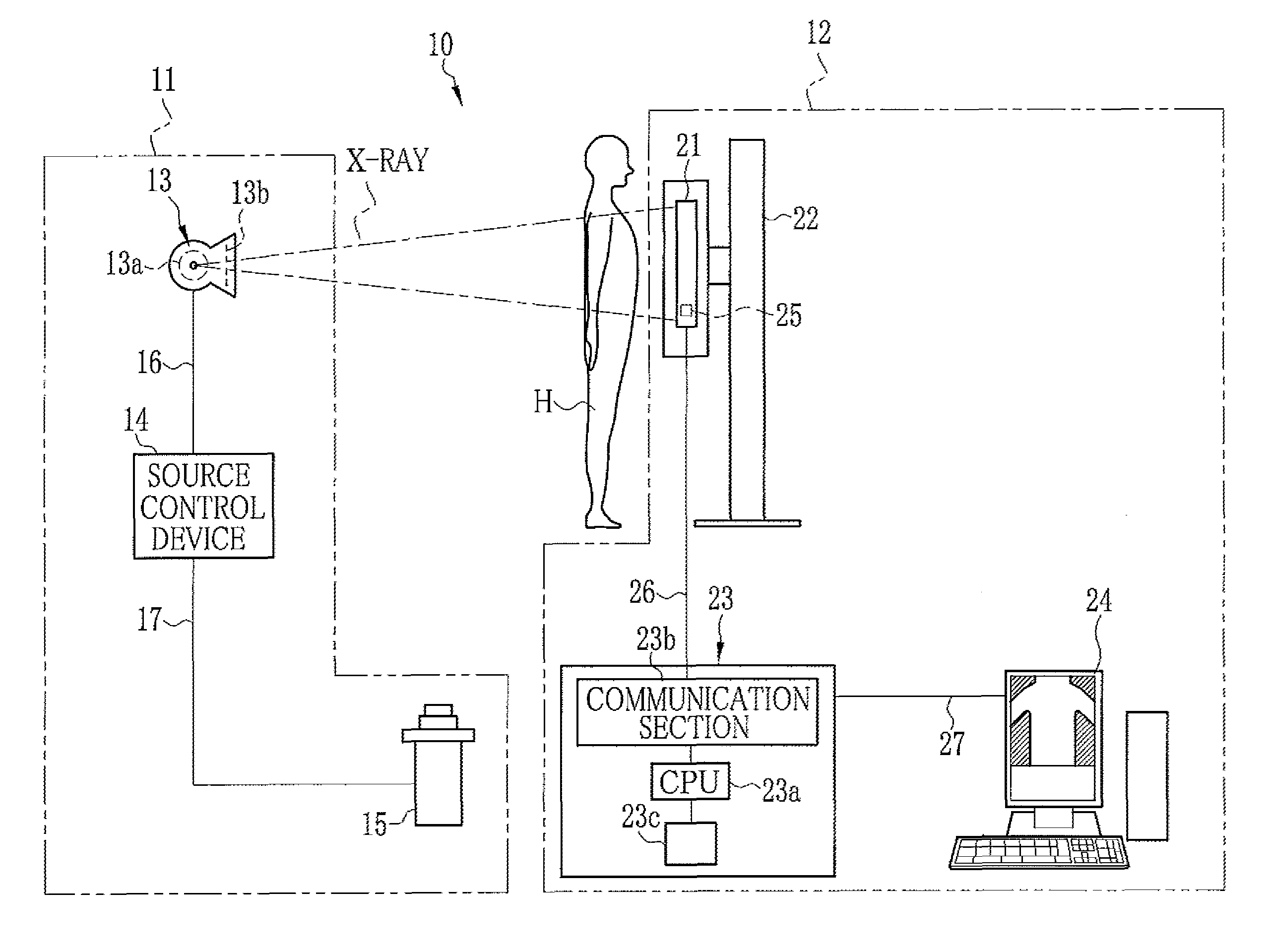
[0039]In FIG. 1, an X-ray imaging system 10 includes an X-ray generating apparatus 11 and an X-ray imaging apparatus 12. The X-ray generating apparatus 11 includes an X-ray source 13, a source control device 14 for controlling the X-ray source 13, and an irradiation switch 15. The X-ray source 13 has an X-ray tube 13a for emitting X-rays and a collimator 13b that limits an X-ray field of the X-rays emitted from the X-ray tube 13a.

[0040]The X-ray tube 13a includes a cathode and an anode (target). The cathode includes a filament for releasing thermoelectrons. When the thermoelectrons hit the target, X-rays are generated. The target is a rotating anode having a disc-shape. The target is rotated such that the focal spot moves along a circular path to disperse heat caused by the impact of the thermoelectrons. The collimator 13b has a plurality of lead plates for shielding the X-rays. The lead plates are arranged in parallel crosses with an irradiation opening formed at its center. The i...


PUM

PropertyMeasurementUnit
timeaaaaaaaaaa
timeaaaaaaaaaa
timeaaaaaaaaaa

Abstract

An acceleration sensor is installed in an electronic cassette. The acceleration sensor detects a shake. When magnitude of the shake, measured using the acceleration sensor, is greater than or equal to a shake detection threshold value, a judging circuit of a shake detecting section turns off a switching element. An operation switching section is disconnected from an irradiation detecting section that detects a start of X-ray irradiation. Thus, an irradiation detection function of the irradiation detecting section is disabled. After a predetermined time, the judging circuit outputs an ON signal to the switching element to turn on the switching element. Thereby, the irradiation detecting section resumes the irradiation detection.

Description

BACKGROUND OF THE INVENTION[0001]1. Field of the Invention[0002]The present invention is related to a radiation image detection device for use in a radiation imaging system and a method for controlling the same.[0003]2. Description Related to the Prior Art[0004]A radiation imaging system, for example, an X-ray imaging system is composed of an X-ray generating apparatus and an X-ray imaging apparatus. The X-ray generating apparatus generates X-rays. The X-ray imaging apparatus captures an X-ray image formed by the X-rays passed through a subject. The X-ray generating apparatus has an X-ray source, a source control device, and an irradiation switch, for example. The X-ray source emits the X-rays to a subject (a patient). The source control device controls the X-ray source. The irradiation switch is used for inputting a command to start X-ray irradiation. The X-ray imaging apparatus has an X-ray image detection device and an imaging control device. The X-ray image detection device dete...

Claims


Application Information

Patent Timeline
Patent Type & Authority Patents(United States)
IPC IPC(8): G01N23/04A61B6/00
CPCA61B6/4233A61B6/4283A61B6/541A61B6/4021A61B6/542H04N23/30H04N5/32
Inventor YOSHIDA, YUTAKA
Owner FUJIFILM CORP
Features
  • R&D
  • Intellectual Property
  • Life Sciences
  • Materials
  • Tech Scout
  • Unparalleled Data Quality
  • Higher Quality Content
  • 60% Fewer Hallucinations
Learn More