Dual draft crane vessel

a crane and crane technology, applied in the field of vessels, can solve the problems of undesired roll motion of vessels and barges, affecting the stability of vessels, so as to reduce the roll motion, improve the stability, and reduce the stiffness and stability

Inactive Publication Date: 2015-02-24
GUSTOMSC RESOURCES BV +1
View PDF11 Cites 5 Cited by
  • Summary
  • Abstract
  • Description
  • Claims
  • Application Information

AI Technical Summary

Benefits of technology

[0012]The crane may be situated near the stern of the vessel such that in the transit mode the arm is supported on the deck of the vessel. In a preferred embodiment the vessel, next to having lifting capabilities, is laid out as a pipe-lay vessel, a pipe transporting trajectory extending in a length direction of the vessel below the crane. In the shallow draft mode, pipe segments can be connected and the pipe can be fed along the firing line to the sea bed. As the shallow draft mode results in reduced roll motions, the pipe lay operations can be continued under high sea states without the need to abandon the pipe. In one embodiment a pipe exit point is situated at the stem, the pipe transporting trajectory in the lifting mode being situated below water level, the exit point being closed by watertight doors. The firing line for the pipe is situated below deck level, leaving free area for voluminous deckloads on the deck. During lifting operations, the pipe exit point is sealed, for instance by a double watertight door.
[0013]In one embodiment according to the invention, lower ballast tanks are situated in the lower section and upper ballast tanks are situated in the upper section, the upper and lower ballast tanks being filled and emptied by the ballast control system, the upper ballast tanks providing an anti-heeling moment during lifting, while the lower ballast tanks being used for draft control. The separate ballast tanks situated at different levels allow optimal positioning of the centre of gravity and buoyancy of the vessel by the ballast control system, to be optimally adapted to the specific operation, be it transit, pipe laying or lifting.
[0014]A double deck is preferably supported on top of substantially flat ballast tanks, with the upper (working) deck at a distance from the top of the tanks. External reinforcement structures on the top of tank provide stiffness and stability. As no support structures have to be included inside the ballast tanks, no air is entrapped in air pockets inside the ballast tanks during ballasting, which results in water movement in the tanks being excluded by which improved stability is achieved. The double deck configuration also allows welding to the upper deck without damaging the anti-corrosion coating on the top of tank.
[0015]In one embodiment counterbalance means are provided on the crane for placing the centre of gravity of the crane and a relatively small load, on a vertical axis of rotation of the crane. In this manner, the crane can lift small loads, such as for instance up to 100 tons, without heel, when the vessel is in the transit mode, while having a rotational freedom of 360°.

Problems solved by technology

This increased width however makes these barges susceptible to wave moments as the natural frequency of these wide vessels is close the average wave period of about 7-8 s. Hence the known lifting vessels and barges have a limited operating window will be subject to undesired roll motions under all conditions.

Method used


Image

  • Dual draft crane vessel
  • Dual draft crane vessel
  • Dual draft crane vessel

Examples


Embodiment Construction

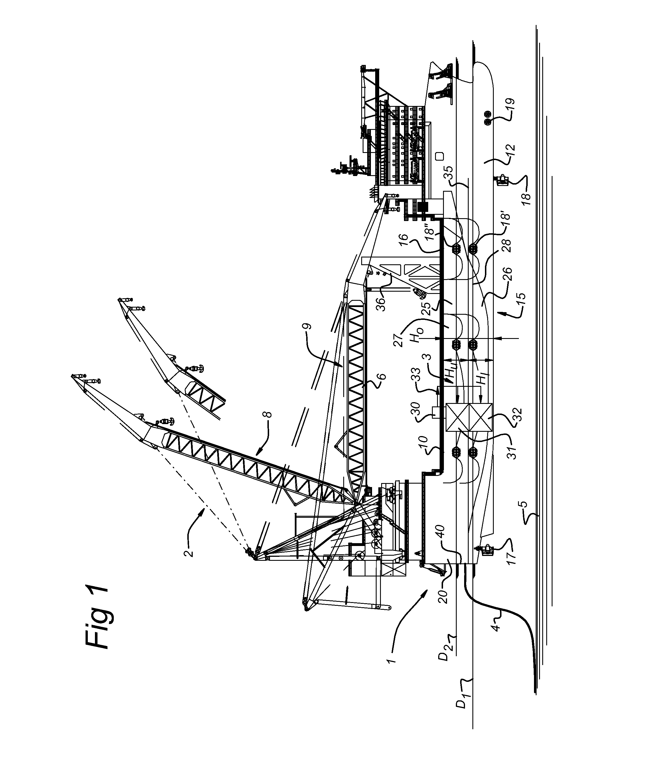
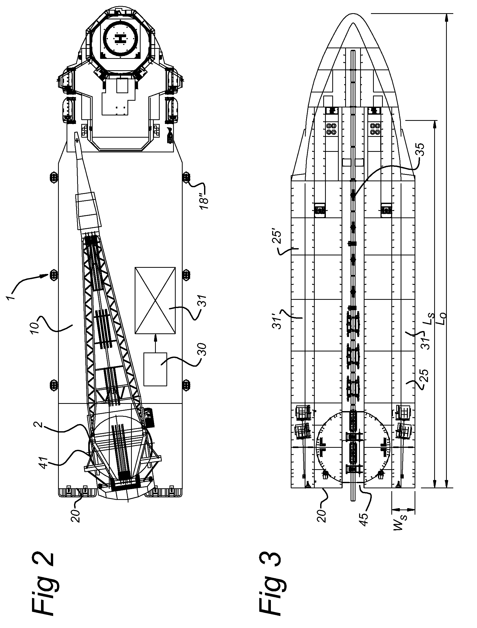
[0023]FIG. 1 shows a lifting and pipe-lay multipurpose vessel 1 having a crane 2 on deck and a firing line 3 for laying of a pipe or cable 4 onto the seabed 5. The arm 6 of the crane 2 can be in a lifting position 8, in which is up righted or can be in the transit position 9, in which it extends generally parallel to the deck 10 of the vessel.

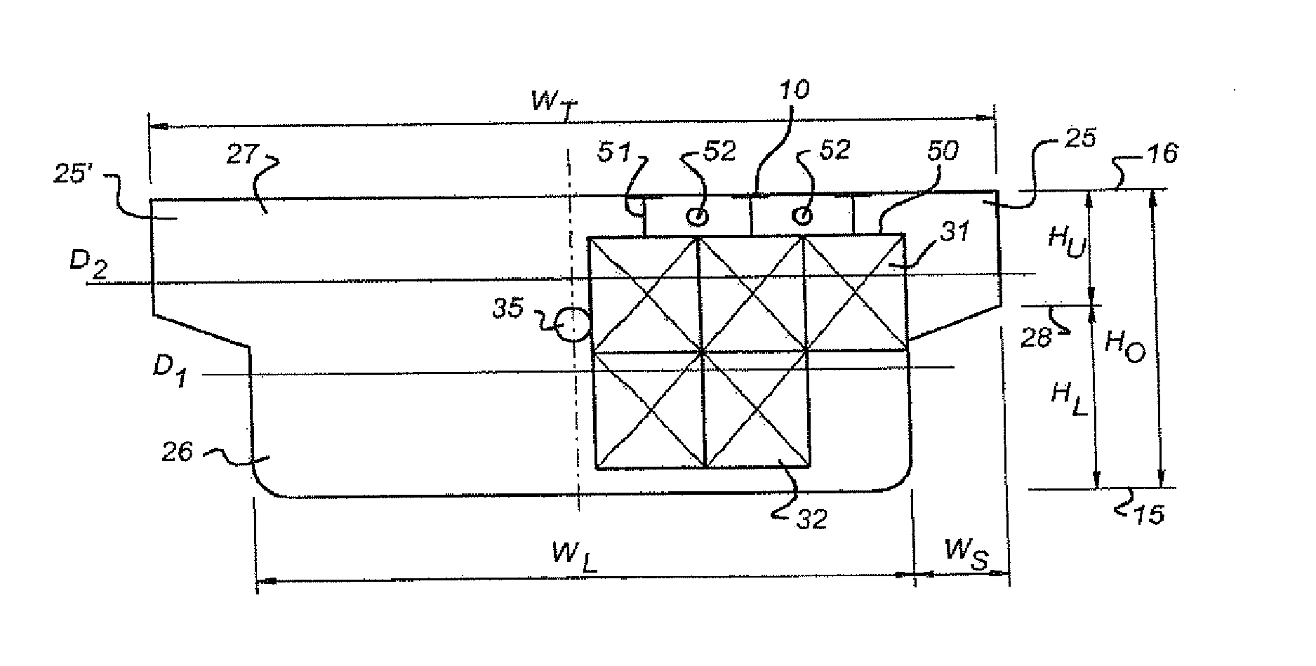
[0024]The hull 12 of the vessel is of a substantially closed surface. With “closed surface” is intended that the hull does not have a columnar structure piercing the waterline, but has as a water line a closed contour. The hull 12 has a relatively narrow lower section 26 of height H1 and a relatively wide top section 27 of height Hu. The wide top section is formed by side extensions 25 extending from a widening level 28 up to deck level 16. The total height of vessel 1 between keel level 15 and deck level 16 is indicated as H0.

[0025]At keel level 15, the vessel is at the stem 20 provided with thrusters 17 for propulsion and with thrusters 18 an...


PUM


Abstract

Vessel including a hull of a substantially closed surface has at deck level a lifting crane, ballast tanks within the hull and a ballast control unit for admitting water to the ballast tanks for changing the draft of the vessel. The hull has a narrow lower section having first width over a height from keel level to a widening level, and a top section having a larger width than the lower section, extending from the widening level upwards towards deck level. The control unit is adapted to ballast the vessel to have a relatively shallow draft level in a transit mode, so that the wide top section is above water level, while the vessel is traveling, and to ballast the vessel to a relatively deep draft level in a lifting mode so that the widening level is below water level, at least when the vessel is substantially stationary and the crane is in its lifting position.

Description

BACKGROUND OF THE INVENTION[0001]1. Field of the Invention[0002]The invention relates to a vessel comprising a hull of a substantially closed surface having at deck level a lifting crane, ballast tanks within the hull and a ballast control system for admitting water to the ballast tanks for changing the draft of the vessel.[0003]2. Description of the Related Art[0004]It is known to float offshore constructions, such a support structures for semi-submersible platforms, to their deployment site a relatively shallow draft level, while the semi submersible support structure is towed by one or more tugs. The support structure comprises two parallel, substantially horizontal ballastable buoyancy bodies and vertical support columns resting on the buoyancy bodies. At the deployment site, the support structure is ballasted to a relatively deep draft level, such that a stable configuration with a low centre of gravity is obtained. A superstructure carrying hydrocarbon processing and / or explor...

Claims


Application Information

Patent Timeline
Patent Type & Authority Patents(United States)
IPC IPC(8): B63B1/04B63B35/03B63B35/44
CPCB63B35/44B63B1/04B63B35/03
Inventor VAN DER VELDE, WILLEM JACOBWASSINK, WILLEM JOHANNES ALAINCOMMANDEUR, JOHAN ALBERT
Owner GUSTOMSC RESOURCES BV
Why Eureka
Try Eureka