Milling tool as well as set of milling inserts of a milling tool

a technology of milling inserts and milling tools, which is applied in the direction of gear teeth, manufacturing tools, manufacturing apparatus, etc., can solve the problems of large stress, large space in the tool body, and weakening of the tool body, and achieve the effect of good surface finish of the machined workpiece and high tool body strength

Inactive Publication Date: 2015-02-24
SANDVIK INTELLECTUAL PROPERTY AB
View PDF6 Cites 4 Cited by
  • Summary
  • Abstract
  • Description
  • Claims
  • Application Information

AI Technical Summary

Benefits of technology

[0011]By this tangential mounting of the flank inserts, the extension of the flank inserts in the axial direction in respect of the rotation axis of the tool will be relatively short, and its extension in the radial, and preferably also in the tangential, direction will be relatively long. The space that is required for the flank insert in the tool body in the axial direction will, therefore, be relatively short in comparison with a radially mounted flank insert, see above mentioned Gear Production Tools, which contributes to a high strength of the tool body. This also means that the active cutting edge of the flank inserts that is in engagement with the workpiece can be made relatively long, which contributes to a high surface smoothness of the machined surface of the workpiece.
[0015]According to a further embodiment of the invention, each flank insert has a fastening hole that extends through the upper side and the under side. Advantageously, each flank insert may then be attached in its respective flank insert seat by means of a fixing screw that extends through the fastening hole into the tool body and that presses the flank insert against the flank insert seat by a press force. Such a fixing screw allows fastening of the flank insert in a reliable way by a relatively large press force. Thanks to the under side of the flank insert being pressed against the bottom surface of the flank insert seat, the axial position of the flank insert, and thereby of the active flank insert edge, can be guaranteed with high accuracy.
[0017]According to a further embodiment of the invention, the fixing screw also presses another edge side section of the flank insert against the inner side surface by a second smaller force component of said press force. Advantageously, the second smaller force component may be smaller than the first smaller force component. However, it should be noted that the first smaller force component and the second smaller force component may be equally, or essentially equally large. Independently of this, it is, however, advantageous that the flank insert is pressed against three surfaces, which contributes to a very high accuracy of the position of the flank insert.
[0020]According to a further embodiment of the invention, the rake face of the root insert extends in an extension plane comprising the primary main cutting edge and the secondary main cutting edge, and the extension plane of each root insert having a normal that is parallel to a tangent of the first line where the same intersects the extension plane. Such a positioning of the root inserts is highly advantageous in respect of the cutting machining and the tolerance level aimed at for the slots to be milled.

Problems solved by technology

Radially mounted flank inserts of the type shown in Gear Production Tools have the disadvantage that they require a large space in the tool body.
Thereby, the tool body weakens and large stresses arise.
Another problem is the difficulty to create space for a proper treatment of the chips formed.
It is furthermore difficult to manufacture the seat for this radial flank insert, particularly for the achievement of a correct axial position of the cutting edge.
Such root inserts have the disadvantage that lateral forces act from different directions for consecutive root inserts.
Thereby, the lateral forces will alternately change the direction and thereby generate an imbalance of the milling tool.
This, in turn, generates a poor surface of the workpiece and a high sound level.
A further disadvantage of such tangentially mounted root inserts is that the cutting edges of the different milling inserts have to overlap each other and thereby there is a risk of groove formation in the workpiece.

Method used


Image

  • Milling tool as well as set of milling inserts of a milling tool
  • Milling tool as well as set of milling inserts of a milling tool
  • Milling tool as well as set of milling inserts of a milling tool

Examples


Embodiment Construction

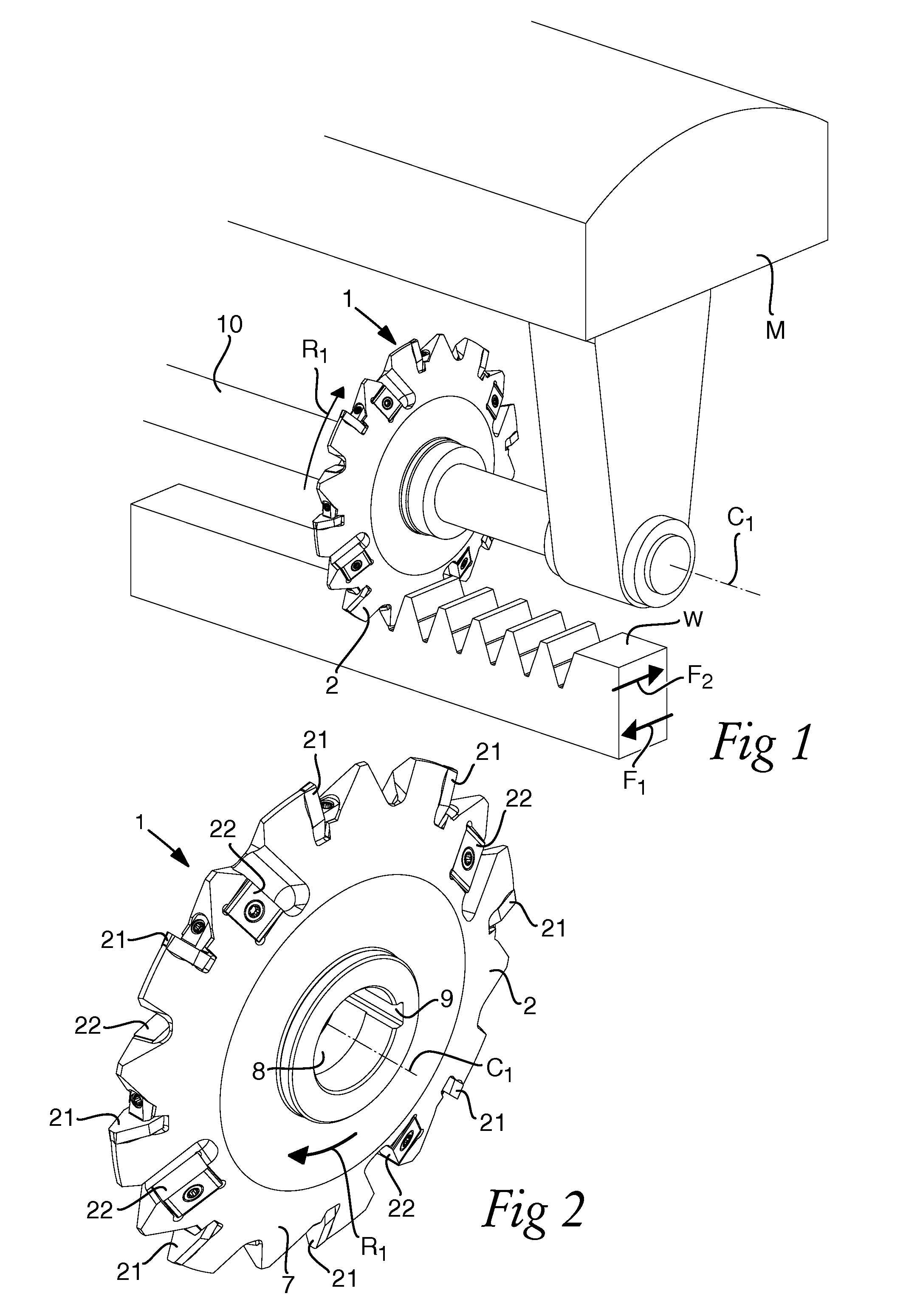
[0050]FIG. 1 shows schematically a machine tool M having a milling tool 1 that is formed for the cutting machining and more precisely for the slot milling of a workpiece W. The milling tool 1 is suitable for the cutting machining of a number of different workpieces W wherein one or more slots is desired, for instance splines, gearwheels, racks, etc.

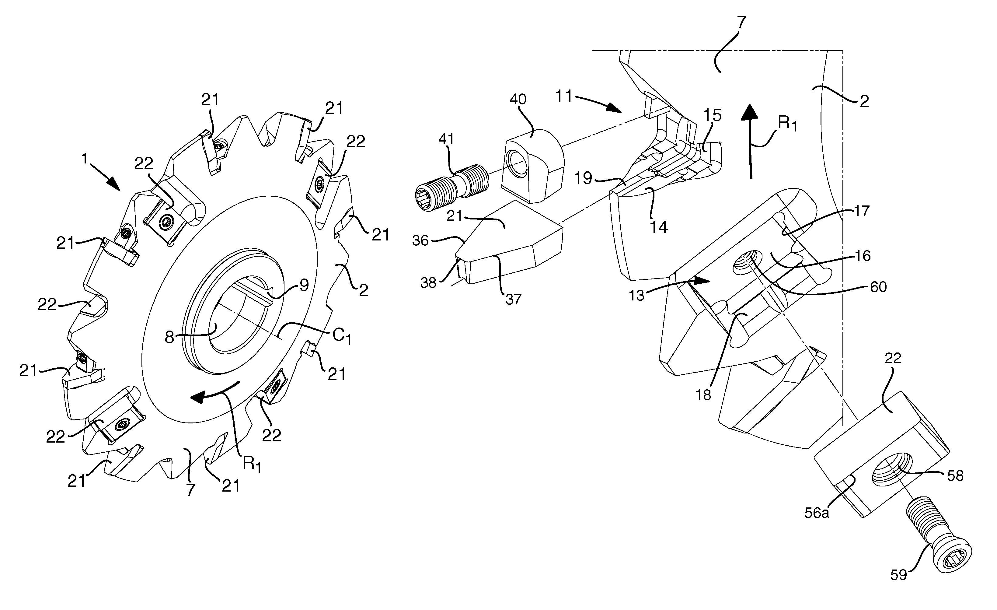
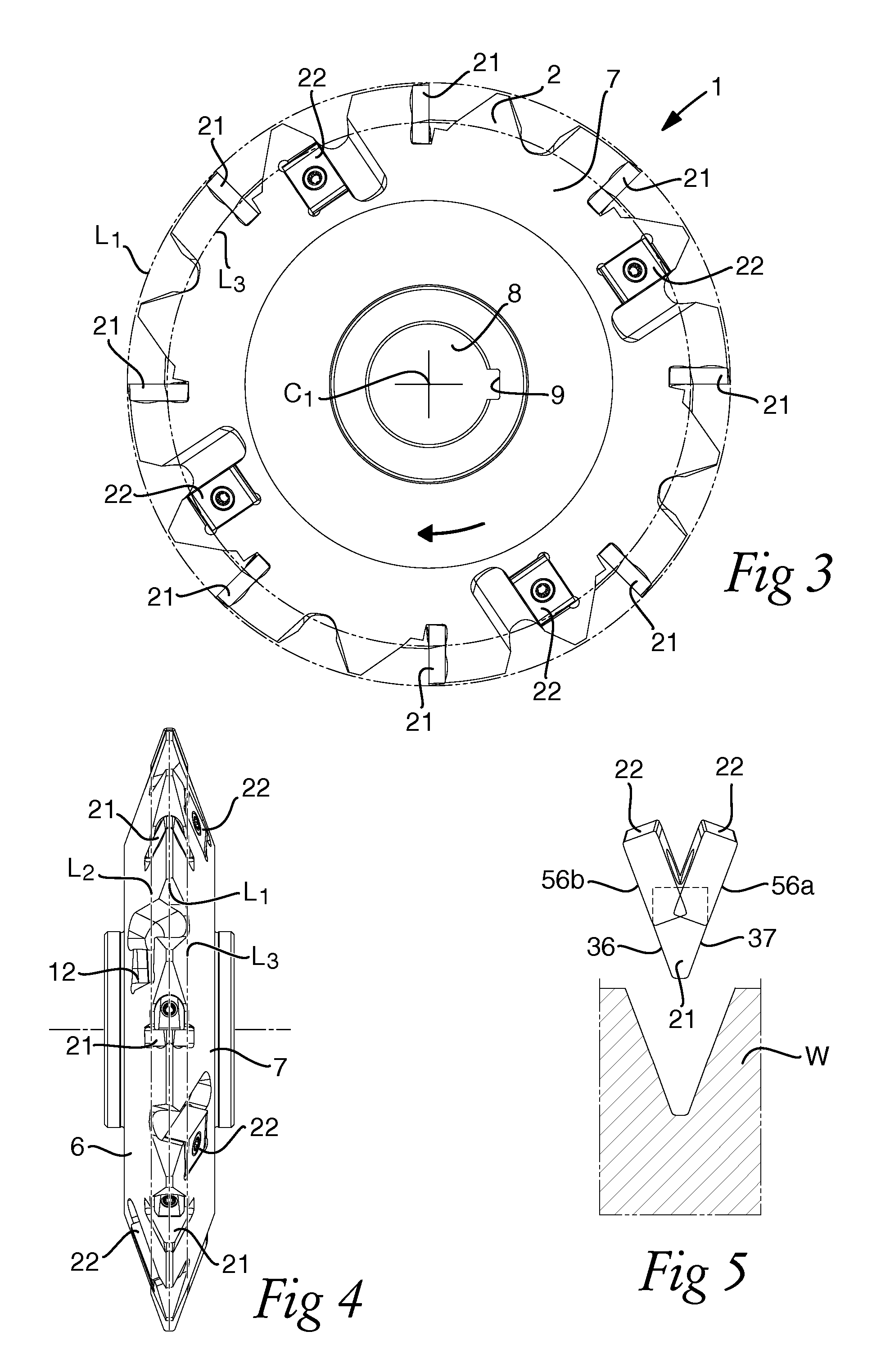
[0051]A first embodiment of the milling tool 1 is shown in more detail in FIGS. 2-8. The milling tool 1 comprises a tool body 2, which may be manufactured from steel, and a large number of replaceable milling inserts 21, 22, which may be manufactured from a material that is harder than steel, for instance, cemented carbide. The tool body 2 defines a rotation axis C1 and has a primary side 6 and an opposite secondary side 7. The rotation axis C1 extends through the primary side 6 and the secondary side 7.

[0052]The milling tool 1 also comprises a through axial hole 8 having a straight groove 9 for the receipt of a rod or drive shaft 10, for...


PUM

PropertyMeasurementUnit
angleaaaaaaaaaa
angleaaaaaaaaaa
angleaaaaaaaaaa

Abstract

A milling tool for slot milling includes a tool body and a plurality of separated first seats, which form root insert seats for root inserts arranged one after the other along a first line and a plurality of separated flank insert seats that includes a plurality of second seats for flank inserts . The plurality of second seats is arranged one after the other along a second line on a primary side of the root insert seats. A plurality of third seats for flank inserts is arranged one after the other along a third line on a secondary side of the root insert seats. Each flank insert seat includes a bottom surface, an inner side surface, and an outer side surface. Each flank insert includes an under side, an opposite upper side, and a circumferential edge side that forms a rake face connecting the upper side and the underside.

Description

RELATED APPLICATION DATA[0001]This application claims priority under 35 U.S.C. §119 to Swedish Patent Application No. 1250448-6, filed on May 4, 2012, which the entirety thereof is incorporated herein by reference.FIELD OF THE INVENTION AND PRIOR ART[0002]The present invention concerns a milling tool for slot milling. The milling tool may be formed as a so-called slot cutter or slitting cutter for the milling of straight or oblique slots, particularly for the manufacture of splines, but the milling tool can also be utilized for the manufacture of gearwheels. More precisely, the invention concerns a milling tool according to the preamble of claim 1 and a set of milling inserts according to the preamble of claim 16.[0003]The brochure Gear Production Tools from Kennametal, p. 21, 2009, shows a milling tool of the type indicated by way of introduction. This known milling tool is formed for the milling of sprocket wheels. The milling tool comprises a tool body defining a rotation axis, a...

Claims


Application Information

Patent Timeline
Patent Type & Authority Patents(United States)
IPC IPC(8): B23C5/08B23C3/00B23C5/20B23C5/22B23F21/12B23F21/14
CPCB23C5/08B23F21/128B23C5/207B23C5/2273B23C5/205B23C5/22B23F21/146B23C2200/0416B23C2200/0494B23C2200/165B23C2200/367B23C2210/168Y10T407/1936Y10T407/235Y10T407/1942Y10T407/19Y10T407/1914Y10T407/192Y10T407/1928B23C5/202B23G5/18
Inventor SAGSTROM, THOMAS
Owner SANDVIK INTELLECTUAL PROPERTY AB
Why Eureka
Try Eureka