Image display apparatus and image display system

a technology of image display and image, which is applied in the field of image display apparatus and image display system, can solve the problems of limiting the movement of the physician's hands, taking a long time to search for an image suitable for the procedure, etc., and achieves the effect of improving the efficiency of the ivr procedur

Active Publication Date: 2015-02-24
TOSHIBA MEDICAL SYST CORP
View PDF32 Cites 7 Cited by
  • Summary
  • Abstract
  • Description
  • Claims
  • Application Information

AI Technical Summary

Benefits of technology

[0007]An object of the invention is to provide an image display apparatus and an image display system capable of improving the efficiency of an IVR procedure.

Problems solved by technology

However, during the procedure, the movement of the physician's hands is restricted since the physician operates the catheter.
However, in this case, it takes a long time to search an image suitable for the procedure.

Method used


Image

  • Image display apparatus and image display system
  • Image display apparatus and image display system
  • Image display apparatus and image display system

Examples


first modification

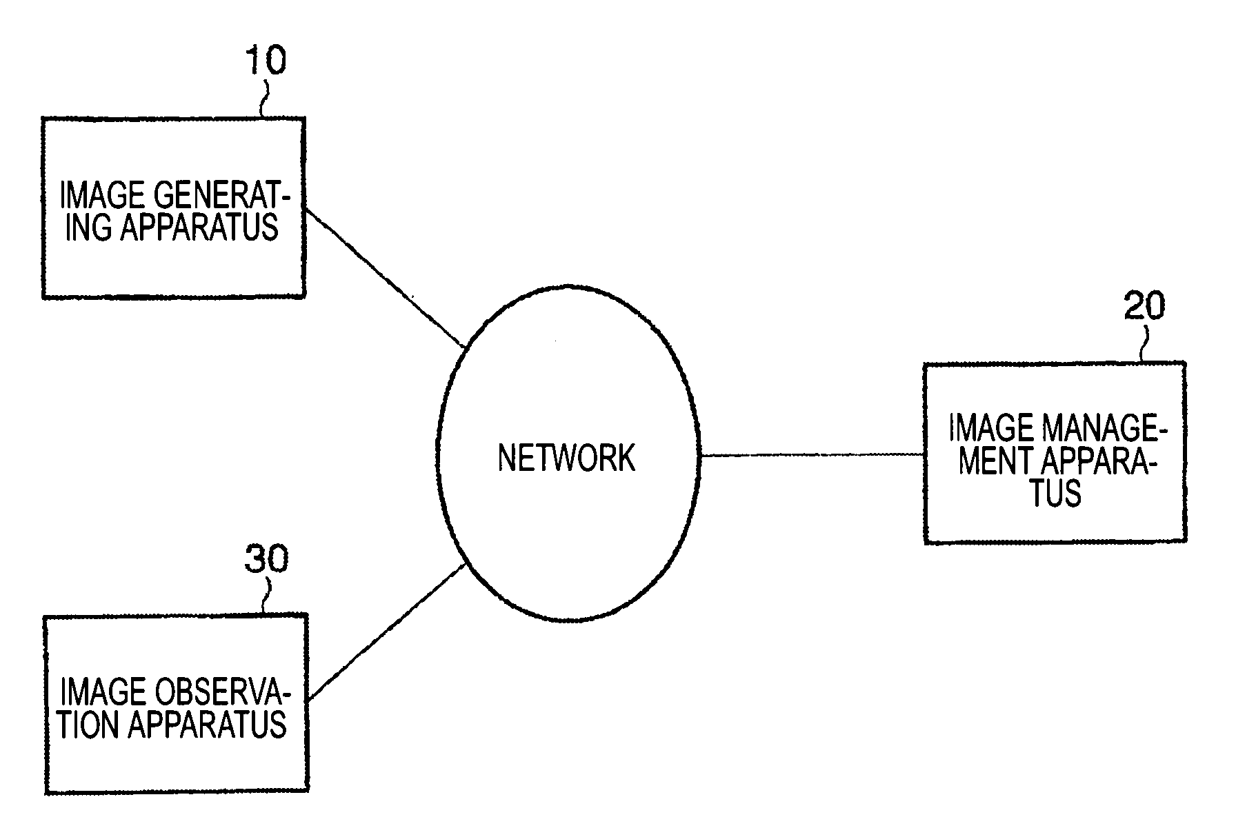
[0089]In a first modification, an example in which a capture position is not added to the image transmitted from the image generating apparatus 10 will be described. FIG. 14 is a diagram illustrating the structure of an image display system according to the first modification. As shown in FIG. 14, the image display system according to the first modification includes the image generating apparatus 10, the image management apparatus 20, the image observation apparatus 30 and a camera apparatus 40. The camera apparatus 40 is installed in an examination room. The camera apparatus 40 captures the image of the leading end of an arm (for example, an X-ray detector) of the image generating apparatus 10 that captures the current image and the image of a bed, and generates video data. The generated video data is transmitted to the image management apparatus 20. The image management apparatus 20 includes an image position calculating unit (not shown). The image position calculating unit calcul...

second modification

[0095]In a second modification, an example in which the image management apparatus 20 cannot receive data of the current image since the data image generating apparatus 10 and the image management apparatus 20 are not connected to each other through a network, or since no image is transmitted during image capture will be described. FIG. 16 is a diagram illustrating an example of the structure of an image display system according to the second modification. As shown in FIG. 16, the image display system includes the image generating apparatus 10, the image management apparatus 20, the image observation apparatus 30, and a camera apparatus 50. The image generating apparatus 10 includes a gantry 11 and a monitor 12. The gantry 11 generates data of the current image during the current IVR procedure. The monitor 12 displays the current image. An output terminal of the monitor 12 is connected to an output terminal of the image observation apparatus 30 by a cable. The data of the current im...

third modification

[0099]In a third modification, an example in which it is difficult to add a capture position to the current image using the methods according to the above-described embodiment and the first modification will be described. In the following description, components having substantially the same functions as those according to the above-described embodiment are denoted by the same reference numerals, and a description thereof will be made if necessary.

[0100]An image display system according to the third modification is based on the concept that the shapes of the main blood vessels of the human body are different from each other according to parts of the human body and it is possible to specify parts of the human body from the shapes of the blood vessels.

[0101]FIG. 19 is a diagram illustrating the structure of an image management apparatus 60 according to the third modification. As shown in FIG. 19, the image management apparatus 60 includes a control unit 21, a communication unit 22, a ...


PUM


Abstract

A storage unit stores data of a plurality of previous images of a plurality of regions generated during a previous catheter procedure. A route map generating unit arranges a plurality of first catheter images or blood vessel images included in the plurality of previous images according to the positional relationship between the plurality of regions to generate a route map indicating the distribution of the plurality of first catheter images or blood vessel images. A specifying unit specifies a specific portion of a second catheter image included in a current image generated during a current catheter procedure. A calculating unit calculates the position of the specified specific portion on the route map on the basis of the positional relationship between the current image and the previous image. A display unit displays a specific previous image corresponding to the calculated position.

Description

CROSS-REFERENCE TO RELATED APPLICATIONS[0001]This application is based upon and claims the benefit of priority from prior Japanese Patent Application No. 2008-021492, filed Jan. 31, 2008, the entire contents of which are incorporated herein by reference.BACKGROUND OF THE INVENTION[0002]1. Field of the Invention[0003]The present invention relates to an image display apparatus and an image display system for supporting a catheter operation.[0004]2. Description of the Related Art[0005]An IVR (Interventional Radiology) procedure using an image generating apparatus, such as an X-ray diagnostic apparatus, to treat a site of lesion has been actively performed. In the IVR procedure, a catheter operation is performed for angioplasty or angioembolization. In recent years, various techniques have been proposed which support an operation of inserting a medical instrument, such as a catheter, into a site of lesion during the IVR procedure (for example, see JP-A-2000-342565). A system for perform...

Claims


Application Information

Patent Timeline
Patent Type & Authority Patents(United States)
IPC IPC(8): G06K9/00A61B6/00A61B6/12G06F19/00G06T5/50G06T7/00
CPCG06F19/3406A61B6/12A61B6/481A61B6/504G06F19/321G06T5/50G06T7/0012A61B6/5235G06T2207/10121G06T2207/20221G06T2207/30021G16H30/20G16H40/63
Inventor FUJII, KOUKIOSADA, MASAKAZUNIWA, KENICHIHORI, SHINICHINAKAGAWA, YOSHIAKI
Owner TOSHIBA MEDICAL SYST CORP
Why Eureka
Try Eureka