Device for comminution of feed material

a technology of comminution device and feed material, which is applied in the direction of cocoa, solid separation, grading, etc., can solve the problems of wear on the inside of the housing wall, the attachment of rotating machine parts to stationary machine parts is problematic, and the friction is considerable at the stationary transverse wall, so as to reduce operating costs and ensure the accessibility to the interior of the housing. , the effect of reducing the operating cos

Inactive Publication Date: 2015-03-17
PALLMANN MASCHFAB GMBH & CO KG
View PDF2 Cites 5 Cited by
  • Summary
  • Abstract
  • Description
  • Claims
  • Application Information

AI Technical Summary

Benefits of technology

[0013]A first advantage of the invention results from the structural feature of displacing the attachment region of the rotating rotors axially inward towards the center of the housing to stationary machine parts, such as to the screen path, specifically while simultaneously creating a free space between the housing and rotor. This measure remedies two serious disadvantages of the above-described prior art at once.
[0014]Firstly, material that gets through the seal gap is returned to the remaining material flow directly and without additional provisions. Consequently, a device according to the invention is characterized by a simplified machine construction and, at the same time, reduced operating expense. Secondly, the thermal problems that have hitherto been known are eliminated by the air gap in the free space between the housing wall and the rotor. The air gap represents thermal insulation for the transverse wall, which consequently no longer heats up as strongly. As a result, temperature-related problems occur to a far lesser degree in an device according to the invention. In an advantageous refinement of this concept, cooling air can flow through the free space, the cooling air being supplied through openings in the housing, for example. In the event that the air flows through the free space from the top to the bottom, the cooling air additionally supports the flow of material.
[0015]The transverse walls represent structurally load-bearing parts, for which the bearing of static and dynamic loads is an important function. By displacing the seal gap axially inward from the plane of the transverse wall (US 2006 / 0118671 A1), the transverse wall can remain without structural weakening, and thus can serve better for load bearing.
[0016]In carrying this concept further, the transverse walls of a device according to the invention can accomplish the mounting of the rotor, for example in that support brackets are attached to the outsides of the transverse walls. This results in an extremely compact construction in which all important components are within or attached to the housing.
[0017]It proves to be an advantage if the transverse walls are connected to one another in a deflection-resistant manner by longitudinal profiles, thus forming a stiff supporting frame. This allows for doors to be installed in the longitudinal sides of the device, through which accessibility to the interior of the housing is ensured.
[0018]It is advantageous for the free space to be closed at both sides and at the top. The surfaces delimiting the free space in this design can be composed of the longitudinal walls and the cover plate, for example. At the top, the closure to the clearance surrounding the upper circumferential section can also be composed of a shaped part, which is located between the metal wearing plate and the transverse wall for the purpose of attachment of the metal wearing plate on the face side. In this way, the material escaping from the seal gap is collected and reunited with the flow of material in a targeted manner.

Problems solved by technology

In machines of this nature, the attachment of rotating machine parts to stationary machine parts proves to be problematic; in particular the attachment of the rotor to the housing proves to be a critical zone with regard to wear, heat buildup within the device, and quality of the end product.
The rotor moving relative to the transverse wall during the course of comminution carries the feed material along in its circular path, which leads to considerable friction at the stationary transverse walls.
The consequences are, firstly, wear on the inside of the housing wall and, secondly, an input of heat into the housing itself, since a portion of the supplied drive energy is converted into friction heat.
This not only leads to additional thermal loading of the device, with the result that measures may need to be taken for cooling, but also leads to reduced energy efficiency.
Thus, while the problem of wear of the housing inner wall is solved to a great extent in such an embodiment, it has nonetheless become apparent that fine feed material gets into the annular gap between the annular disk and the housing wall, and in this way the annular gap clogs in the course of time.
In order to limit frictionally caused wear and heat development in the annular gap, it is necessary to clean it at regular time intervals, with the disadvantage that the expenditure of time required for this purpose increases the downtime of the device.
Nevertheless, during the course of comminution, especially fine particles get into the gap and reemerge on the outside of the housing.
It proves to be a disadvantage here that the material escaping from the outlet from the seal gap, and hence from the housing, is separated from the remaining flow of material by the transverse wall, and consequently must be recaptured by additional peripheral machine components and delivered to further processing, which entails additional structural and processing costs.
From a static perspective, the transverse wall is structurally weakened by the large opening in which the annular disk is located, which impairs the stiffness of the machine construction.
The opening also has the result that the rotor cannot be mounted on the transverse walls of the housing, the rotor instead having to be mounted directly on the substratum.
The metal ducts attached to the transverse walls are not static load-bearing machine parts such as, e.g., the transverse walls, and consequently cannot be used for mounting the rotor.
With regard to cleaning and maintenance that are as fast and effective as possible, the metal ducts on the outsides of the transverse walls only make for additional projections and corners that make such tasks more difficult.

Method used


Image

  • Device for comminution of feed material
  • Device for comminution of feed material
  • Device for comminution of feed material

Examples


Embodiment Construction

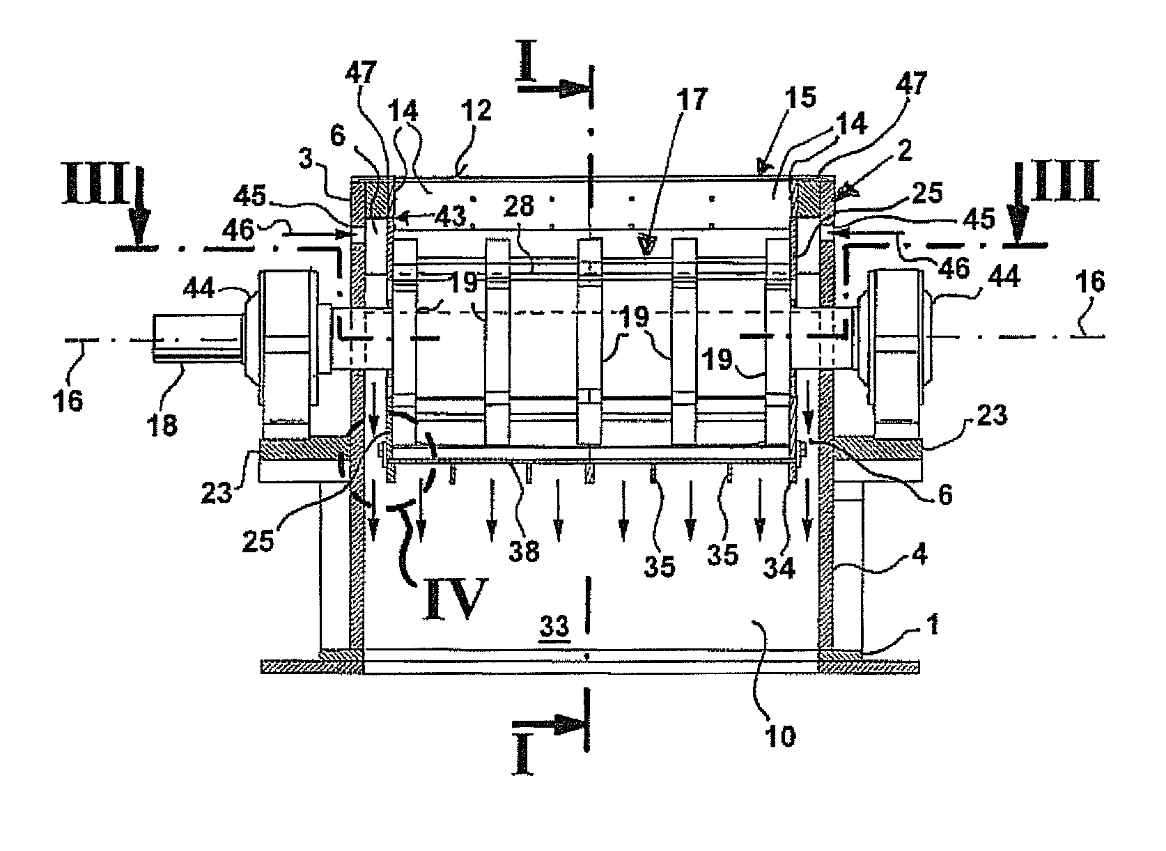
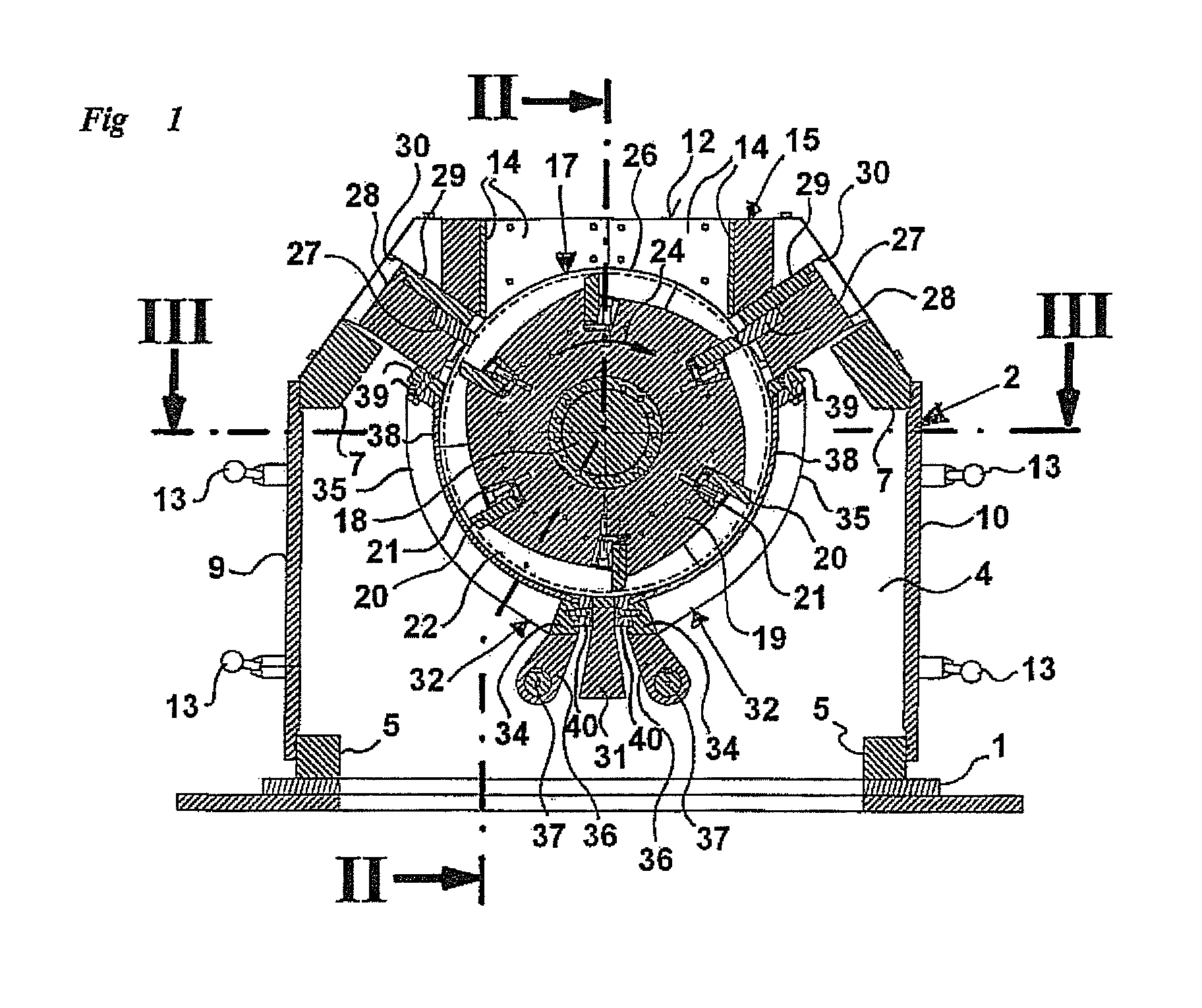
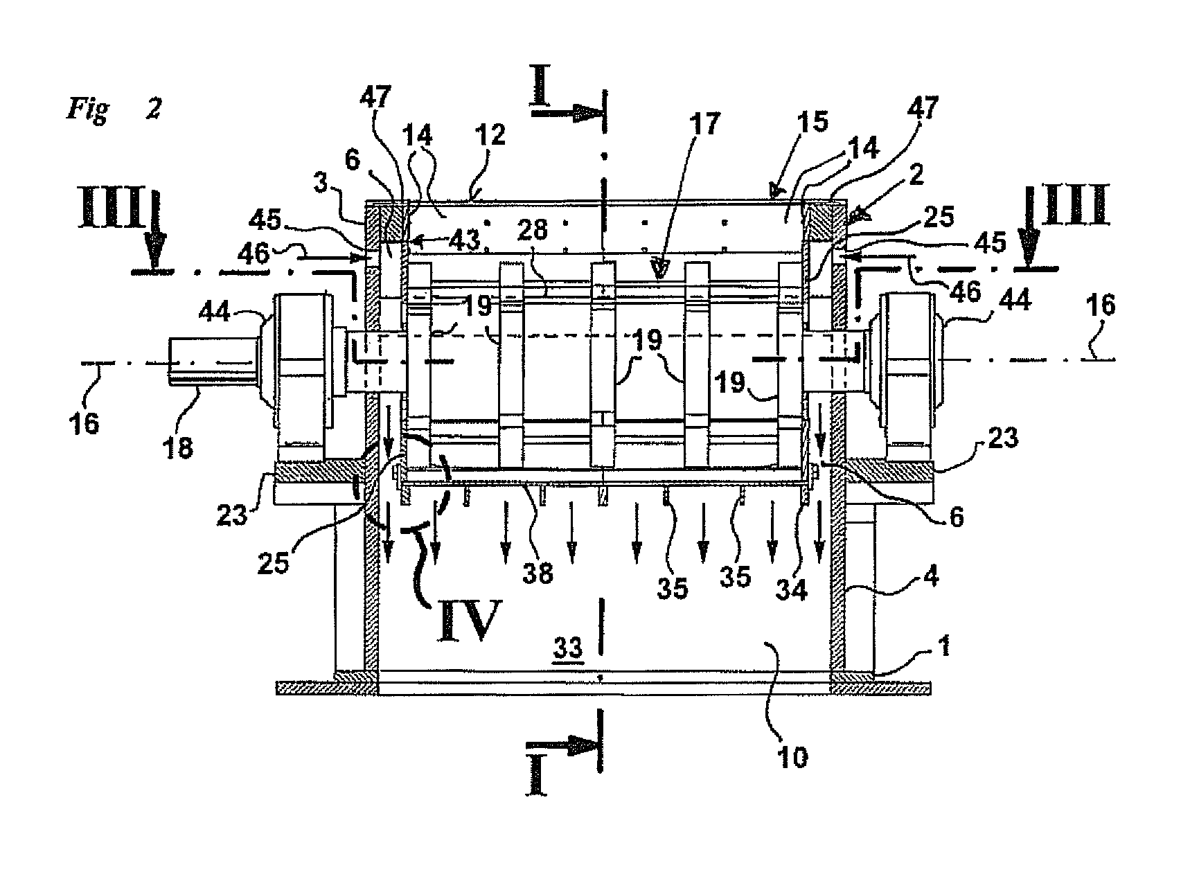
[0030]The more precise structure of the inventive device is evident from FIGS. 1 through 4, which show a cutting mill. The cutting mill has, resting on a substructure labeled 1, a housing 2 which is composed essentially of two opposing, plane-parallel transverse walls 3 and 4, whose outline is rectangular in the bottom region and trapezoidal in the top region (FIG. 1). The transverse walls 3 and 4 are structurally load-bearing parts, which are frictionally connected to one another at their base region by one longitudinal spar 5 on each side. In the transition region between the rectangular region and the trapezoidal region, longitudinal spars 7, which likewise are axially parallel, reinforce the housing construction, with the overall result of a stiff supporting frame. Each of the longitudinal sides of the housing 2 are closed off by longitudinal walls 9 and 10, which can pivot about a vertical axis by means of hinges 11 after the lock 13 has been released in order to ensure accessi...


PUM


Abstract

A device for comminuting feed material is provided that has a housing including longitudinal walls and transverse walls for accommodating a rotor that rotates about a longitudinal axis. The rotor is equipped about its circumference with processing tools, and has, on its faces, an annular disk, each of which is concentric to the longitudinal axis. Within the housing, at least one screen path extends over a part of the circumference of the rotor, each screen path running at a slight radial distance from the annular disks while forming a seal gap. The feed material is supplied to the rotor through a feed shaft and is directed out of the device via a material discharge extending downstream of the screen path. In order to return material that emerges through the seal gap to the remaining material flow annular disks are each arranged with an axial clearance A from the transverse walls.

Description

[0001]This nonprovisional application claims priority under 35 U.S.C. §119(a) to German Patent Application No. DE 10 2010 045 125.8, which was filed in Germany on Sep. 12, 2010, and which is herein incorporated by reference.BACKGROUND OF THE INVENTION[0002]1. Field of the Invention[0003]The invention relates to a device for comminuting feed material.[0004]2. Description of the Background Art[0005]Such devices belong to the field of mechanical process engineering, in particular the comminution of feed material in the manner of cutting, clipping, tearing, or crushing. But the dissociation of the bond of composite materials, which is always accompanied by a comminution of the feed material, also resides within the scope of the present invention. Generic devices consequently are suitable for the comminution of piece goods and bulk materials, in particular plastics with and without admixtures, wood, waste wood, paper, cardboard, cellulose, textiles, waste material, vulcanized rubber, nat...

Claims


Application Information

Patent Timeline
Patent Type & Authority Patents(United States)
IPC IPC(8): B02C18/22B02C18/14B02C18/16B02C18/18B02C23/16
CPCB02C18/144B02C2023/165B02C2018/188B02C2018/162
Inventor PALLMANN, HARTMUT
Owner PALLMANN MASCHFAB GMBH & CO KG
Why Eureka
Try Eureka