Cable connector and cable assembly, and method of manufacturing cable assembly

a technology of cable connectors and cable assemblies, which is applied in the direction of fixed connections, coupling device details, coupling device connections, etc., can solve the problems of manufacturing problems and the possibility of electrical characteristics variation among cables for differential signal transmission, and achieve the effect of reducing the number of parts and being convenient to conn

Inactive Publication Date: 2015-03-17
HITACHI METALS LTD
View PDF3 Cites 4 Cited by
  • Summary
  • Abstract
  • Description
  • Claims
  • Application Information

AI Technical Summary

Benefits of technology

[0008]A preferred aim of the present invention is to provide a cable connector, a cable assembly, and a method of manufacturing the cable assembly, whose electric characteristics are stabilized by suppressing elastic deformation of a cable for differential signal transmission and which is easily connectable by reducing the number of parts.
[0023]According to the present invention, the outer-conductor adhering portion is provided in the ground contact so as to be protruded from the side wall portion of the connector board and to be adhered with the outer conductor by the conductive adhesive, and therefore, it is not required to swage the shield connection terminal so as to be along with the shape of the outer conductor as conventional, so that the electric characteristics can be stabilized by suppressing the elastic deformation of the cable for differential signal transmission. Also, the conventional shield connection terminal is not required, and therefore, the connection work between the outer conductor and the ground contact can be simplified as reducing the number of parts. Further, the soldering connection work for electrically connecting the outer conductor with the ground contact is not required, either, and therefore, thermal deformation of the cable for differential signal transmission due to exposure to a high temperature is prevented.

Problems solved by technology

However, since the shield connection terminal is swaged along with the shape of the outer conductor, the insulator inside the outer conductor is elastically deformed by a swaging force in some cases, which results in occurrence of a problem in manufacture such as change of a distance between the respective signal line conductors inside the insulator.
As a result, a problem of variation in electric characteristics among the cables for differential signal transmission may occur for each product.

Method used


Image

  • Cable connector and cable assembly, and method of manufacturing cable assembly
  • Cable connector and cable assembly, and method of manufacturing cable assembly
  • Cable connector and cable assembly, and method of manufacturing cable assembly

Examples


first embodiment

[0041]Hereinafter, the present invention will be explained in detail with reference to the drawings.

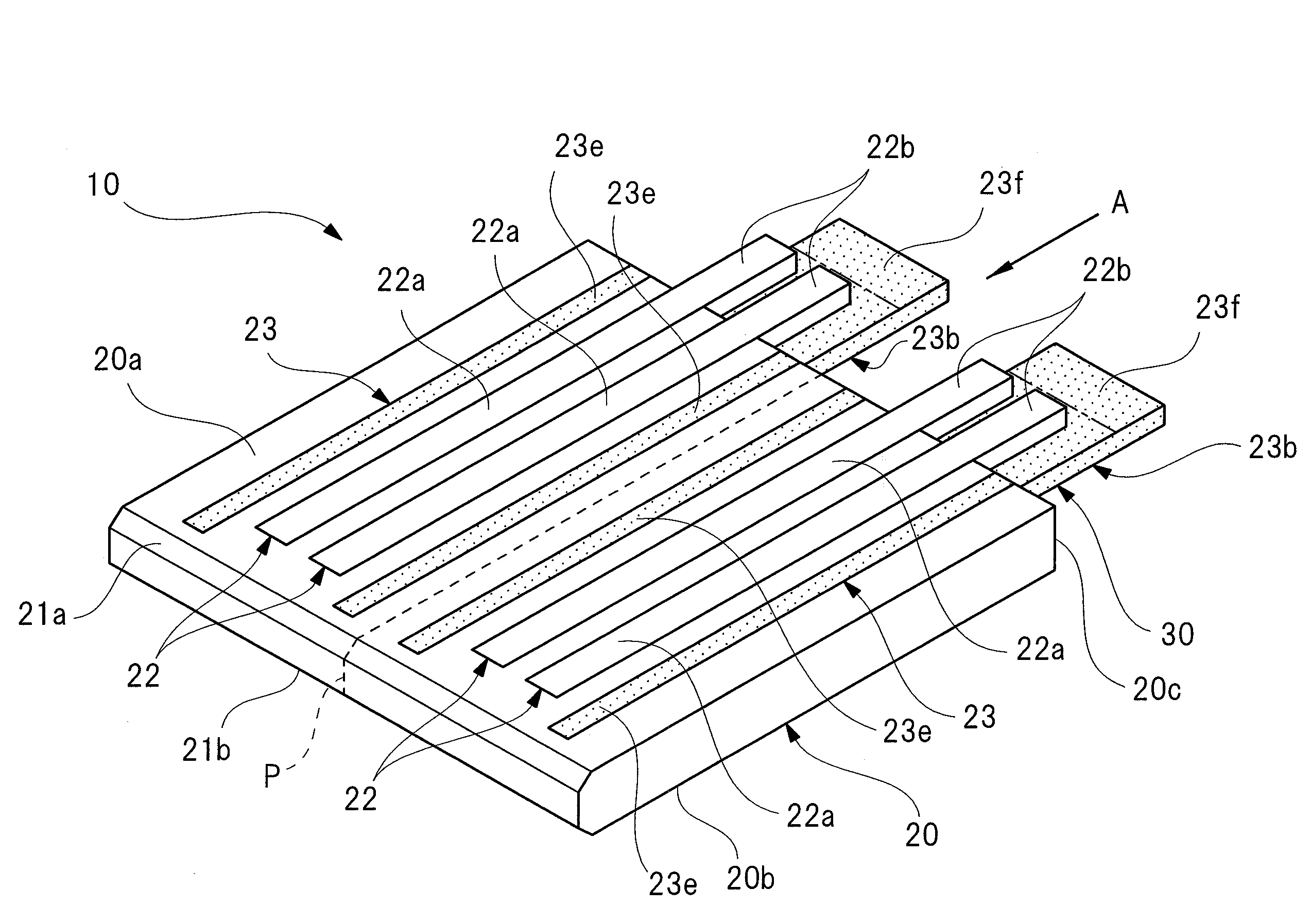
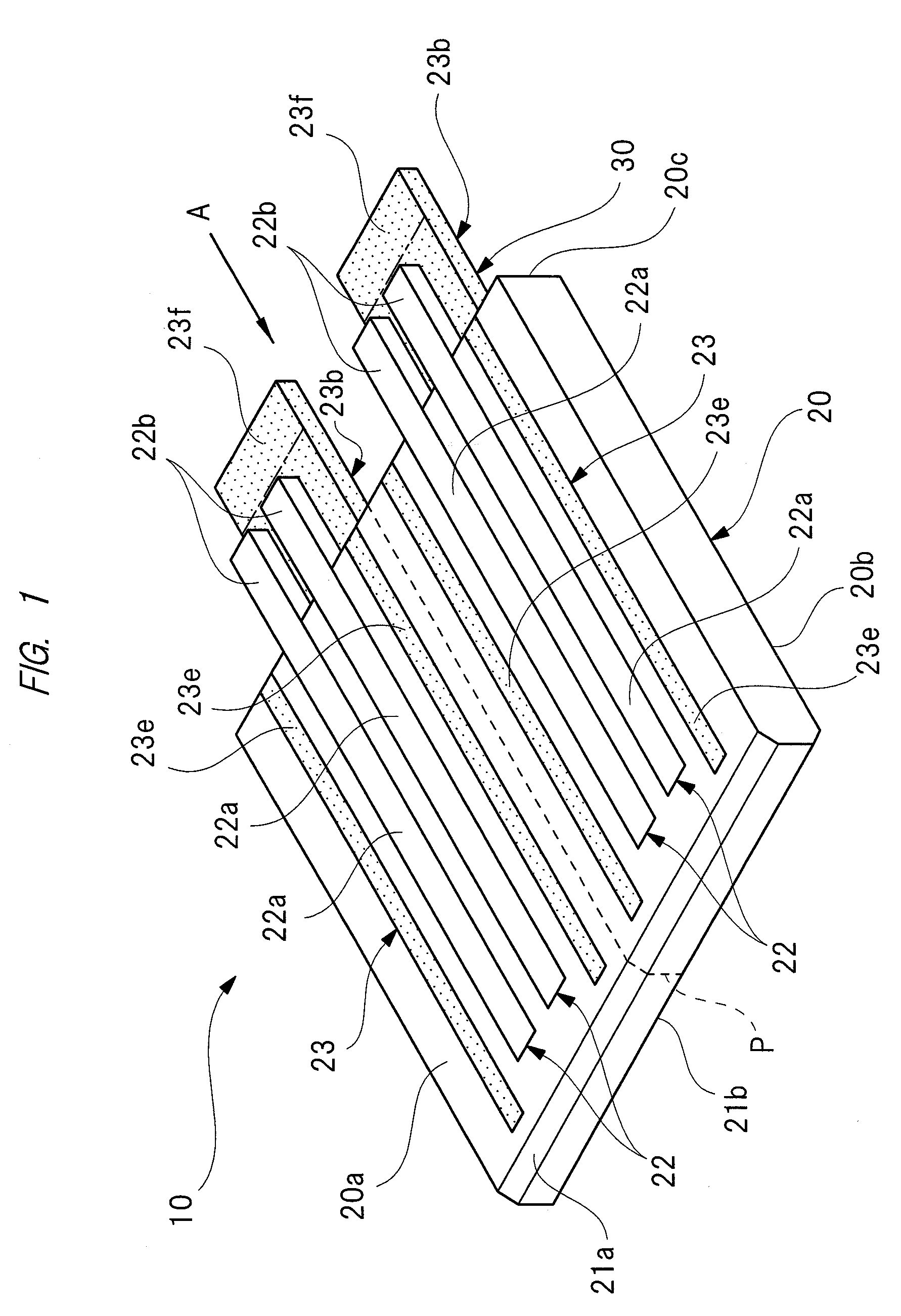
[0042]FIG. 1 is a perspective view of a cable connector according to the first embodiment as viewed from a front side, FIG. 2 is a perspective view of the cable connector of FIG. 1 as viewed from a rear side, FIG. 3 is a side view on an arrow A in FIG. 1, FIG. 4A is a perspective view of a ground contact as viewed from a front side, FIG. 4B is a perspective view of the ground contact as viewed from a rear side, FIG. 5A is a perspective view of a cable for differential signal transmission, FIG. 5B is a cross-sectional view of the cable for differential signal transmission, FIG. 6 is a perspective view for explaining a manufacturing procedure (assembling procedure) of a cable assembly, FIG. 7 is a side view on an arrow B in FIG. 6, and FIG. 8 is a side view on an arrow C in FIG. 6.

[0043]As illustrated in FIG. 1 or 3, a cable connector 10 is provided with a connector main body (connector...

second embodiment

[0087]Note that the shape of the ground contact 23 as illustrated can be also easily formed by performing the pressing work once so that the punching and the forming are simultaneously performed.

[0088]Even in the cable connector 50 according to the second embodiment formed as described above, the same function effect as that of the above-described first embodiment can be achieved. In addition to this, in the second embodiment, the electric connection between the outer conductor 43 and the conductive adhesive G can be further robust, and the electric characteristics can be further stabilized. Also, an adhering area between the outer conductor 43 and the conductive adhesive G can be increased, and therefore, the cable for differential signal transmission 40 can be hard to detach from the outer-conductor adhering portion 23f.

[0089]Next, a third embodiment of the present invention will be described in detail with reference to the drawings. Note that the parts having the same functions...

third embodiment

[0090]FIG. 14 illustrates a perspective view illustrating a cable assembly according to the

[0091]As illustrated in FIG. 14, a cable assembly “CA1” according to the third embodiment is different from the cable assembly CA according to the first embodiment (see FIG. 6) in only that the connection portion between the respective signal line conductors 41 and the respective protruding portions 22b and the connection portion between the outer conductor 43 and the outer-conductor adhering portion 23f are solidified by, for example, thermosetting epoxy resin as the insulating material. More specifically, the peripheries of the respective signal line conductors 41 and the respective protruding portions 22b and the peripheries of the outer conductor 43 and the outer-conductor adhering portion 23f are solidified by the epoxy resin in a substantially rectangular parallelepiped shape, so that a mold resin portion 60 is formed.

[0092]Here, the mold resin portion 60 is formed by performing the abov...


PUM

PropertyMeasurementUnit
angleaaaaaaaaaa
conductiveaaaaaaaaaa
conductive propertyaaaaaaaaaa

Abstract

Provided is a cable connector, a cable assembly, and a method of manufacturing the cable assembly, in which electric characteristics are stabilized by suppressing elastic deformation of a cable for differential signal transmission, and besides, which is easily connectable by reducing the number of parts. In a ground contact, an outer-conductor adhering portion which is protruded from a side wall portion of a connector main body and which is adhered with an outer conductor by a conductive adhesive is provided. In this manner, elastic deformation of a cable for differential signal transmission is suppressed, so that electric characteristics can be stabilized. Also, connecting work between the outer conductor and the ground contact can be simplified as reducing the number of parts. Further, the cable for differential signal transmission is not exposed to a high temperature of soldering or others, and therefore, thermal deformation thereof does not occur, either.

Description

CROSS-REFERENCE TO RELATED APPLICATION[0001]The present application claims priority from Japanese Patent Application No. 2012-261955 filed on Nov. 30, 2012, the content of which is hereby incorporated by reference into this application.TECHNICAL FIELD OF THE INVENTION[0002]The present invention relates to a cable connector provided with a pair of signal line conductors and electrically connected with a cable for differential signal transmission which transmits differential signals whose phases are inverted to each other by an angle of 180°, relates to a cable assembly provided with the cable for differential signal transmission and the cable connector, and relates to a method of manufacturing the cable assembly.BACKGROUND OF THE INVENTION[0003]Conventionally, a differential interface standard such as LVDS (Low Voltage Differential Signal) is adopted in a device such as a server, a rooter, and a storage product, which handles a high-rate digital signal of several Gbit / s or higher, an...

Claims


Application Information

Patent Timeline
Patent Type & Authority Patents(United States)
IPC IPC(8): H01R3/00H01R4/04H01R9/03H01R12/62H01R43/02H01R43/26
CPCH01R43/26H01R4/04H01R9/034H01R43/0207H01R12/62Y10T29/49176Y10T29/49174H01R13/65914
Inventor NONEN, HIDEKIISHIMATSU, YOSUKENISHIMURA, KEI
Owner HITACHI METALS LTD
Why Eureka
Try Eureka