
Apparatus for chemical vapor deposition

a technology of chemical vapor and apparatus, which is applied in the direction of chemical vapor deposition coating, coating, coating process, etc., can solve the problem of sagging in the middle of the shower head in the pecvd apparatus, and achieve the effect of reducing the thermal expansion distortion of the shower head and good quality of uniform large-area thin film

Active Publication Date: 2015-03-17
DMS CO LTD
View PDF4 Cites 278 Cited by
  • Summary
  • Abstract
  • Description
  • Claims
  • Application Information

AI Technical Summary

Benefits of technology

The invention helps minimize the distortion of a shower head caused by temperature changes. This results in a higher quality, large-area thin film.

Problems solved by technology

However, The CVD methods are more commonly used because the PVD methods have the uniformity of composition or thickness and the step coverage that are not as good as those of the CVD methods.
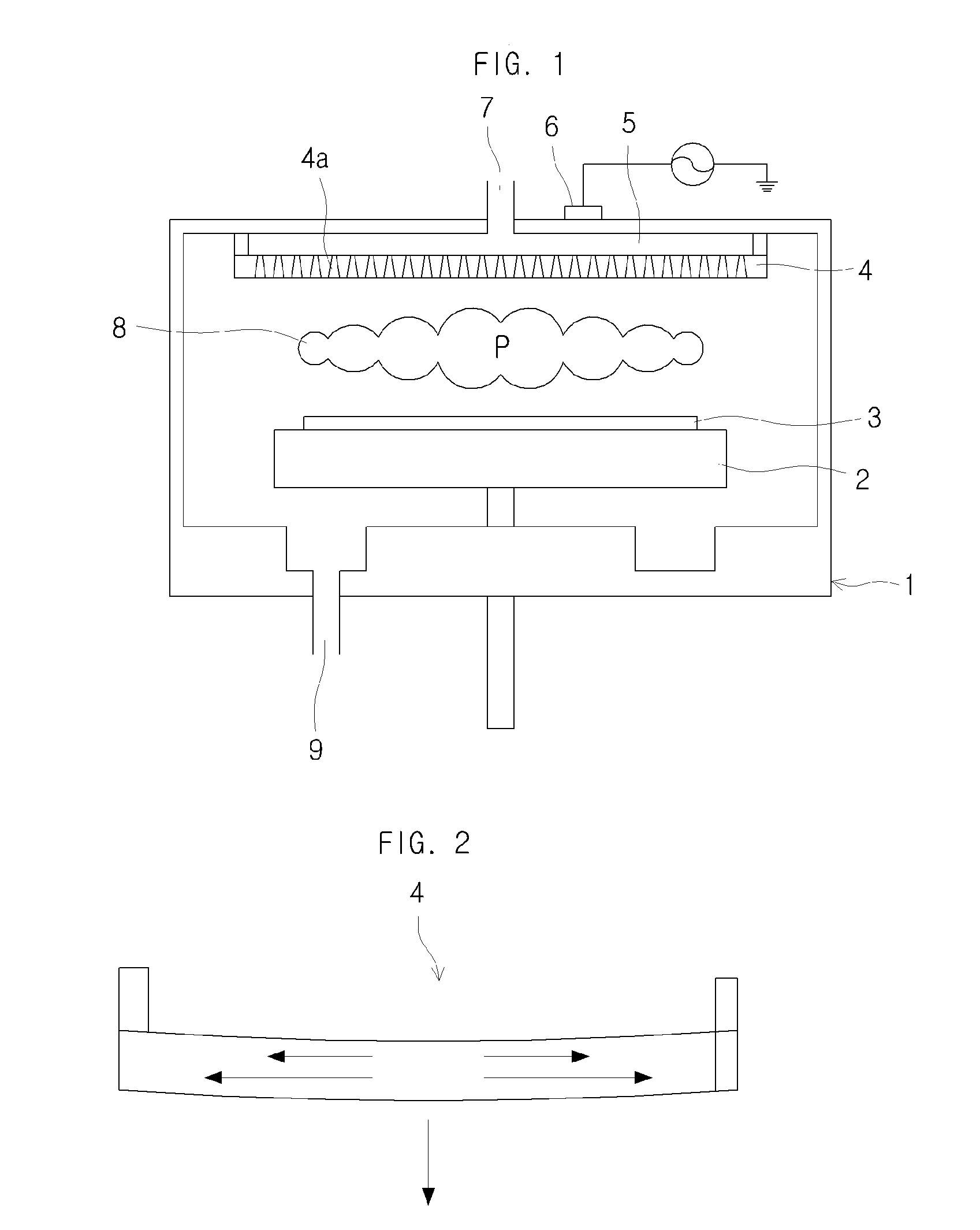
However, as shown in FIG. 2, the shower head 4 in the PECVD apparatus has a problem of sagging in the middle due to its own weight and thermal deformation.

Method used


Image

  • Apparatus for chemical vapor deposition
  • Apparatus for chemical vapor deposition
  • Apparatus for chemical vapor deposition

Examples


Embodiment Construction

[0063]Since there can be a variety of permutations and embodiments of the present invention, certain embodiments will be illustrated and described with reference to the accompanying drawings. This, however, is by no means to restrict the present invention to certain embodiments, and shall be construed as including all permutations, equivalents and substitutes covered by the ideas and scope of the present invention. Throughout the description of the present invention, when describing a certain technology is determined to evade the point of the present invention, the pertinent detailed description will be omitted.

[0064]Terms such as “first” and “second” can be used in describing various elements, but the above elements shall not be restricted to the above terms. The above terms are used only to distinguish one element from the other.

[0065]The terms used in the description are intended to describe certain embodiments only, and shall by no means restrict the present invention. Unless cl...


PUM

PropertyMeasurementUnit
sizeaaaaaaaaaa
thicknessaaaaaaaaaa
thicknessaaaaaaaaaa

Abstract

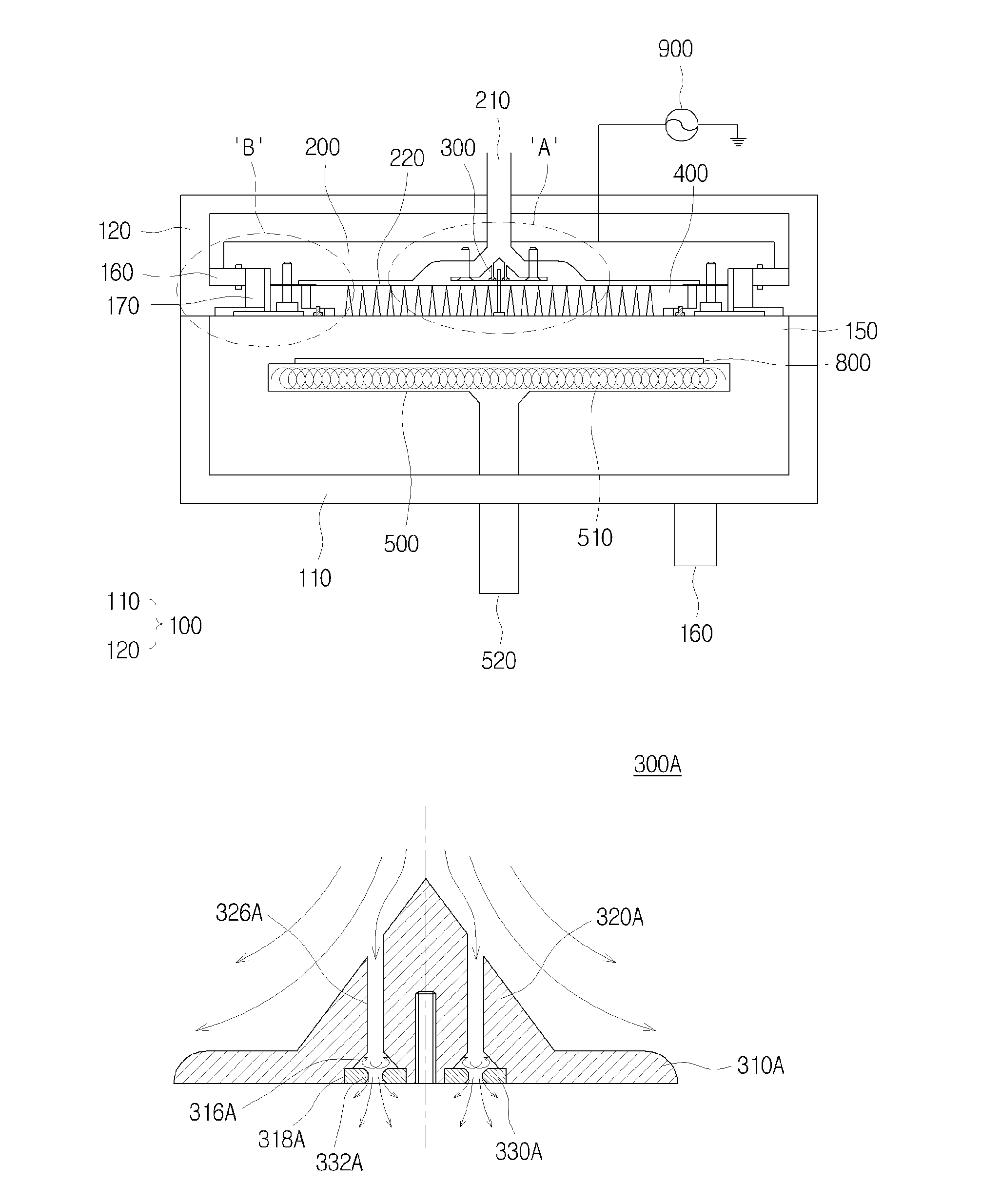
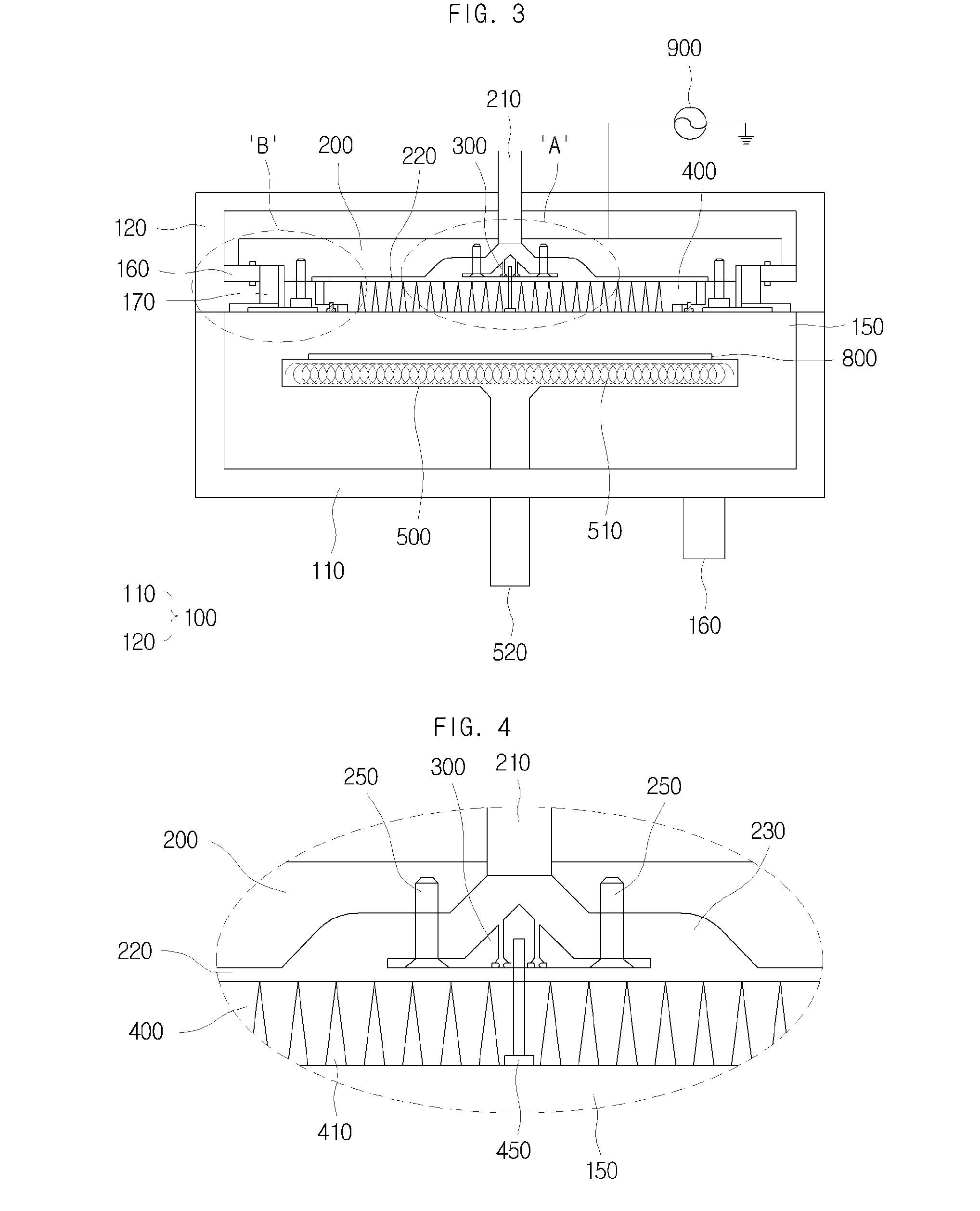
An apparatus for chemical vapor deposition is disclosed. An aspect of the present invention provides an apparatus for chemical vapor deposition that includes: a process chamber configured to demarcate a reaction space; a back plate placed above the reaction space and having a gas inlet in a middle thereof; a gas diffusion member arranged below and separated from the gas inlet and coupled to the back plate by a first coupling member and configured to diffuse process gas supplied through the gas inlet; a shower head placed below and separated from the back plate and the gas diffusion member and having a middle part thereof coupled to the gas diffusion member by a second coupling member and having a plurality of spray holes perforated therein; and a susceptor arranged below and separated from the shower head and supporting a substrate. The gas diffusion member has a plurality of gas guiding holes that vertically penetrate the gas diffusion member such that the process gas supplied through the gas inlet is diffused toward a lower side of the gas diffusion member.

Description

CROSS-REFERENCE TO RELATED APPLICATIONS[0001]This application claims the benefit of Korean Patent Application No. 10-2011-0002779, filed with the Korean Intellectual Property Office on Jan. 11, 2011, the disclosure of which is incorporated herein by reference in its entirety.TECHNICAL FIELD[0002]The present invention is related to an apparatus for chemical vapor deposition.BACKGROUND ART[0003]Methods for forming a thin film on an object can be generally divided into Physical Vapor Deposition (PVD) methods, such as sputtering, in which a thin film is formed in such a way that the physical properties of a deposition source and the physical properties of a thin film material are identical, and Chemical Vapor Deposition (CVD) methods, in which a thin film is formed using a chemical reaction in such a way that the physical properties of a deposition source and the physical properties of a thin film material are different.[0004]However, The CVD methods are more commonly used because the P...

Claims


Application Information

Patent Timeline
Patent Type & Authority Patents(United States)
IPC IPC(8): C23C16/455
CPCC23C16/45559C23C16/45565C23C16/455C23C16/44H01L21/0262
Inventor HUH, YUN-SUNGPARK, SEUNG-IL
Owner DMS CO LTD
Learn More