Subsurface intelligent cluster of current energy converters

a current energy converter and subsurface technology, applied in the direction of electric generator control, machines/engines, mechanical equipment, etc., can solve the problems of not being able to intelligently seek and remain in the peak velocity region of ocean currents, changing ocean currents with time in location, depth and speed, and little advance in using ocean current energy, etc., to achieve the effect of increasing the total power generation, increasing the capacity of power generation, and no net torqu

Active Publication Date: 2015-03-17
SOONG YIN SHANG
View PDF48 Cites 5 Cited by
  • Summary
  • Abstract
  • Description
  • Claims
  • Application Information

AI Technical Summary

Benefits of technology

[0005]The invention relates to a configuration of a cluster of current energy converters. The cluster is towed by a cable behind a mother ship 1 which is anchored in a current 2 in FIG. 1. The cluster consists a serial or nodes 3 connected by a single cable 4 that serves both for electric power and signal transmissions. The current energy converters, equipped with rotors 5, 6 and connecting generators 7, 8 attached to each node 3 like wings to an airplane body FIG. 2. Each rotor looks like a so-called Savonius wind turbine (only two blades shown for illustration). As each rotor rotates in current, the connecting generator converts kinetic energy to electricity. The two rotors in each pair FIG. 3 always rotate in opposite direction, one 5 in clockwise direction but the other 6 in counter-clockwise direction. The opposite rotation is due to the drag force difference on the two rotors' blades. There is no net torque on the node from the two opposing rotations if they rotate at the same rate. There are at least two pairs, four converters, one pair on each side, for a working node FIG. 2. There could be more than two pairs on each node to increase the capacity of power generation. But there must be equal number of pairs on both side of a node for symmetry. There could be many nodes in the cluster to further increase the total power generation. Each node and each converter are designed to be near average water density and therefore neutrally buoyant. A node, with the same number of pairs of converters on both sides of the node, behaves like an ‘airplane flying’ in water.
[0006]In each pair, the two rotors will rotate independently. If both rotors in the pair rotate at the same rate, this pair will remain at the same depth in a current. However, if one rotor rotates faster than the other one in the pair, this pair will either ascend or descent, according to Bernoulli principle (Batchelor, 2000) that says pressure is higher for slow...

Problems solved by technology

There has been, however, little advance in using ocean current energy although various ideas were known since the discovery of strong current such as the Gulf Stream.
One critical difficul...

Method used


Image

  • Subsurface intelligent cluster of current energy converters
  • Subsurface intelligent cluster of current energy converters
  • Subsurface intelligent cluster of current energy converters

Examples


Embodiment Construction

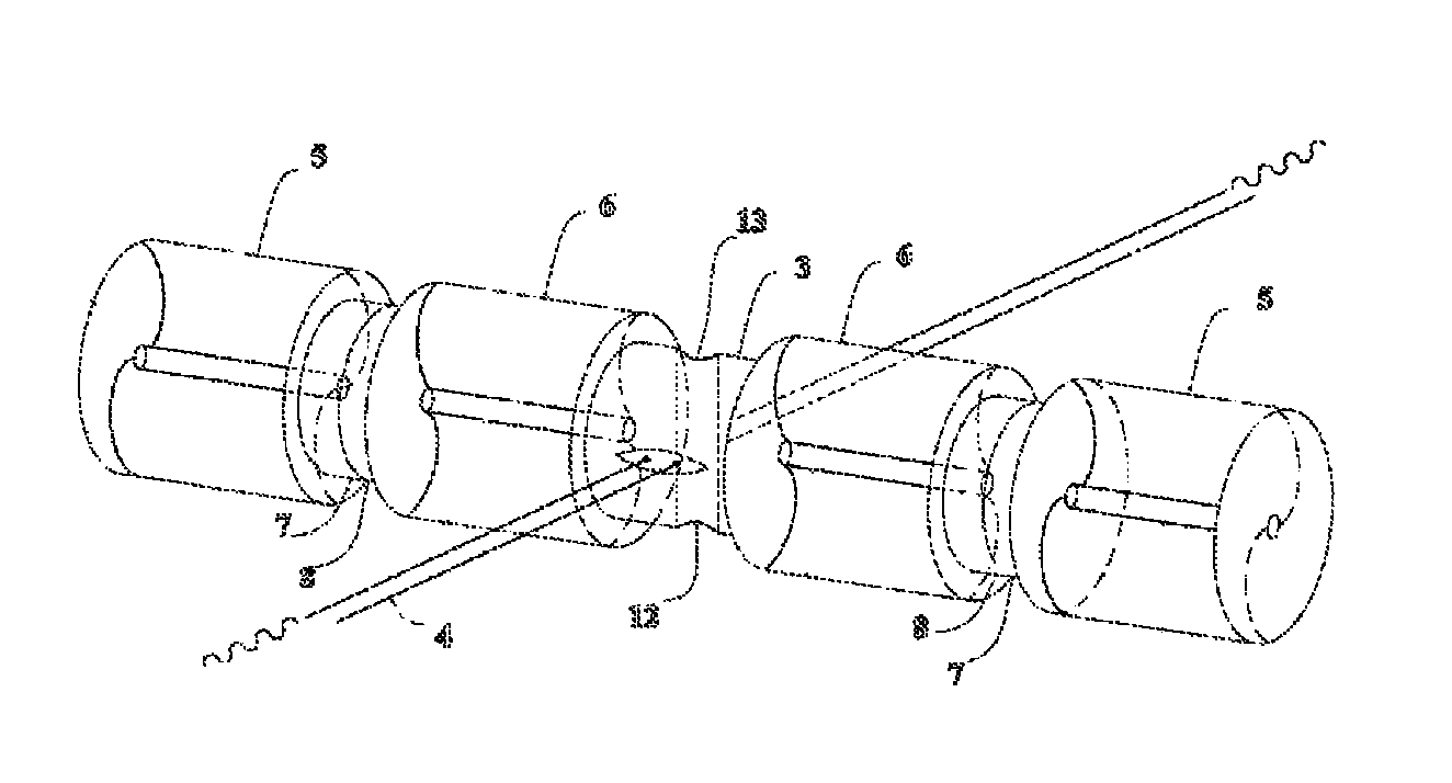
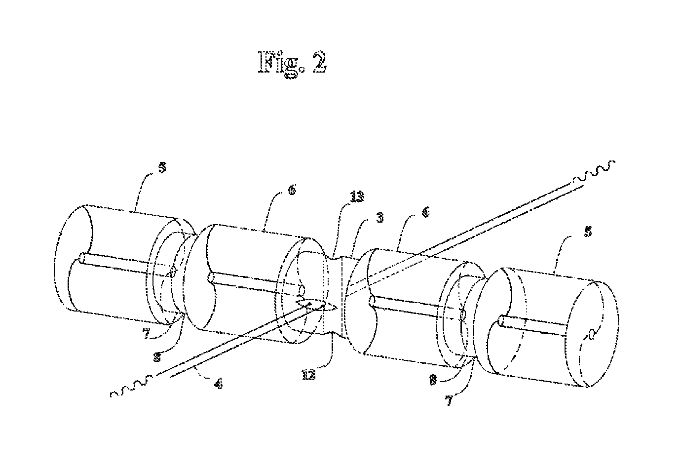
[0016]The invention relates to an application of Bernoulli principle on each pair of rotors that rotate in opposite direction independently. FIG. 3 is used to illustrate this principle in details. When current flow pushes both rotors into rotation in opposite directions because of the drag force is larger on the top blade than that on the bottom blade in rotor 5 but it is exactly the opposite in rotor 6. The two rotors are rotating with the same rate when the resistances due to respective electrical generators 7, 8 are the same. The average flow speeds above and below the two rotors are the same because the two rotors rotate in opposite directions at the same rate. Therefore, Va equals Vb, that leads to Pa equals Pb according to Bernoulli equation, Eq. 1.

0.5(Va)2+Pa / ρ=0.5(Vb)2+Pb / ρ  Eq. 1

where Va and Vb are speed, Pa and Pb are pressure, and ρ is water density.

[0017]However, rotor 5 rotates slower when the resistance increases in the connecting generator 7. This is accomplished by t...


PUM


Abstract

A subsurface floating cluster of current energy converters is disclosed. A cluster consists of many nodes on a single mooring cable. Two converters, rotating in opposite direction, are connected as a pair. At least two pairs, four converters, are connected to each node. Each converter consists of a rotor with curved blades, a transmission, and an electrical generator. A computer on the mother ship, that tows the cluster, controls the rotating rate of every rotor in the cluster. Each node moves vertically or horizontally according to the rotation-rate-differential in each pair of rotors. Each node seeks and remains in peak velocity region, or at a predetermined water depth, to convert kinetic energy to electricity with an optimal efficiency. This invention has characteristics of simplicity in design, using artificial intelligence to achieve high efficiency in peak speed region of an ocean current, incremental capacity, and mobility.

Description

BACKGROUND OF THE INVENTION[0001]1. Field of the Invention[0002]The present invention relates generally to a mooring system and supporting devices to convert ocean current energy to electricity.[0003]2. Description of Related Art[0004]The use of kinetic energy in water flow has been known for many years in human history. The physical principle is simple and it is easy to construct a machine to tap the river flow energy. Ancient people used flow in river to do work for them with a water wheel. There has been, however, little advance in using ocean current energy although various ideas were known since the discovery of strong current such as the Gulf Stream. One critical difficulty is the fact that ocean currents change with time in location, depth and speed. Many patented designs, such as in Haining (U.S. Pat. No. 5,440,176) and Geary, (U.S. Pat. No. 6,006,518) are anchored devices on the seafloor at a fixed location. Mouton (U.S. Pat. No. 4,219,303) and Jennings and Martin (U.S. Pat...

Claims


Application Information

Patent Timeline
IPC IPC(8): F03B13/00H02P9/04F03B13/10F03B17/06
CPCF03B13/10F03B17/063Y02E10/22Y02E10/28F05B2240/95Y02E10/20Y02E10/30
Inventor SOONG, YIN SHANG
Owner SOONG YIN SHANG
Why Eureka
Try Eureka